Chevrolet Sonic Repair Manual: Brake Pressure Modulator Valve Replacement
- Removal Procedure
-
Warning:
Refer to Brake Fluid Irritant Warning.
Caution:
Refer to Brake Fluid Effects on Paint and Electrical Components Caution.
Caution:
Always connect or disconnect the wiring harness connector from the EBCM/EBTCM with the ignition switch in the OFF position. Failure to observe this precaution could result in damage to the EBCM/EBTCM.
- Place the ignition switch in the OFF position.
- Remove the battery tray. Refer to Battery Tray Replacement.
- Clean the area surrounding the EBCM/BPMV of any accumulated dirt and debris.
- Disconnect the EBCM electrical connector.
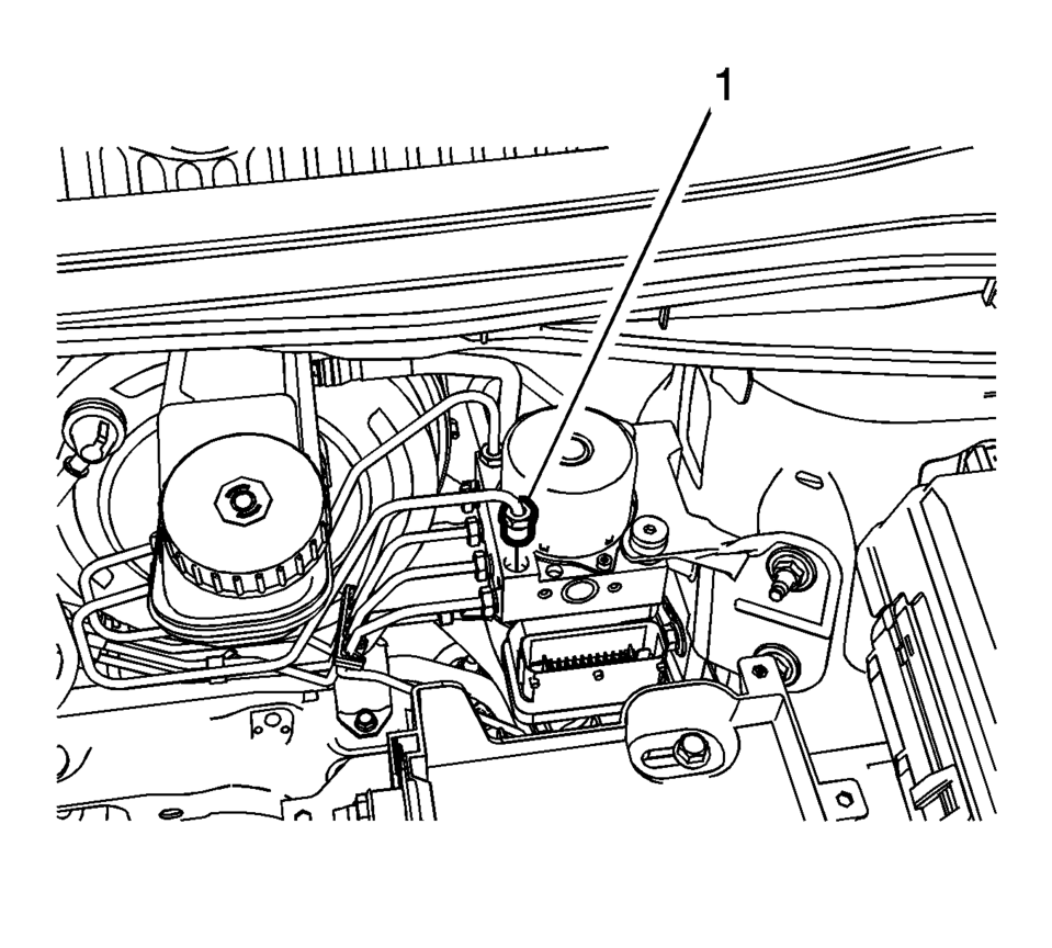
- Disconnect the master cylinder secondary brake pipe fitting (1) from the BPMV.
- Cap the brake pipe fitting and plug the BPMV inlet port to prevent brake fluid loss and contamination.
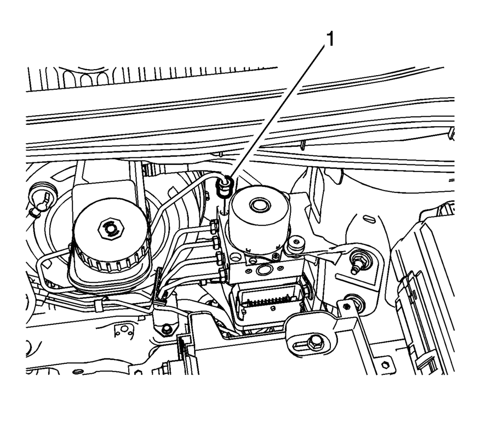
- Disconnect the master cylinder primary brake pipe fitting (1) from the BPMV.
- Cap the brake pipe fitting and plug the BPMV inlet port to prevent brake fluid loss and contamination.
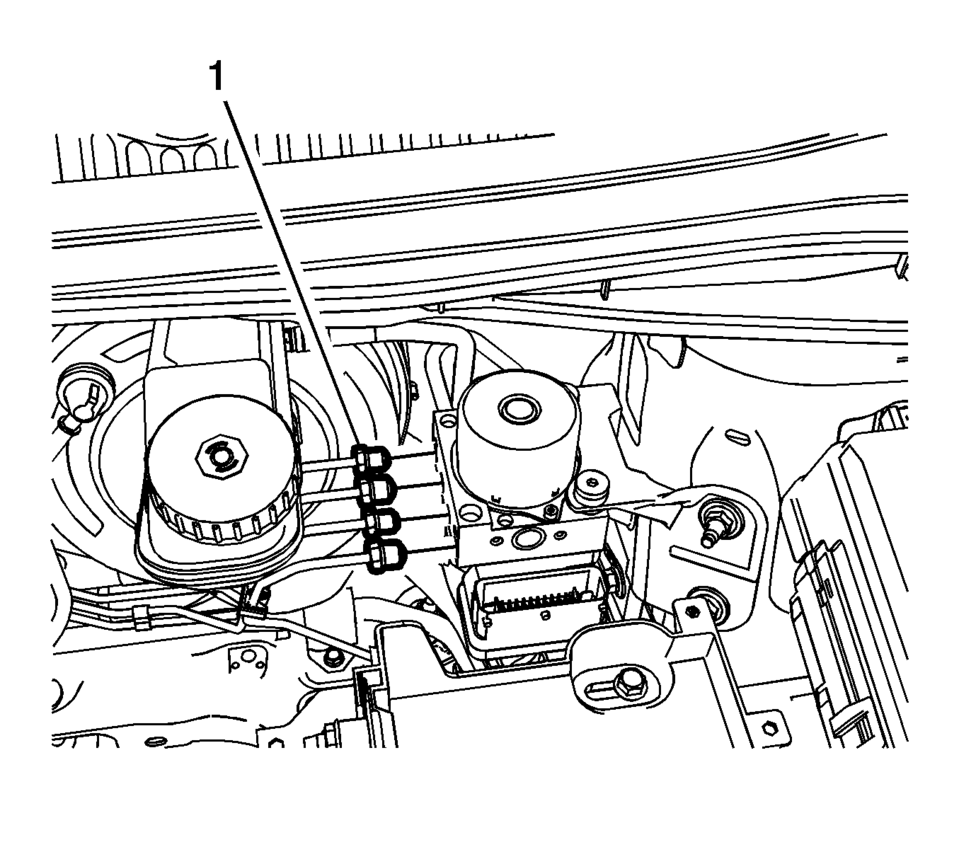
- Reference mark the BPMV outlet brake pipe fittings (1) and disconnect the fittings.
- Cap the brake pipe fittings and plug the BPMV outlet ports to prevent brake fluid loss and contamination.
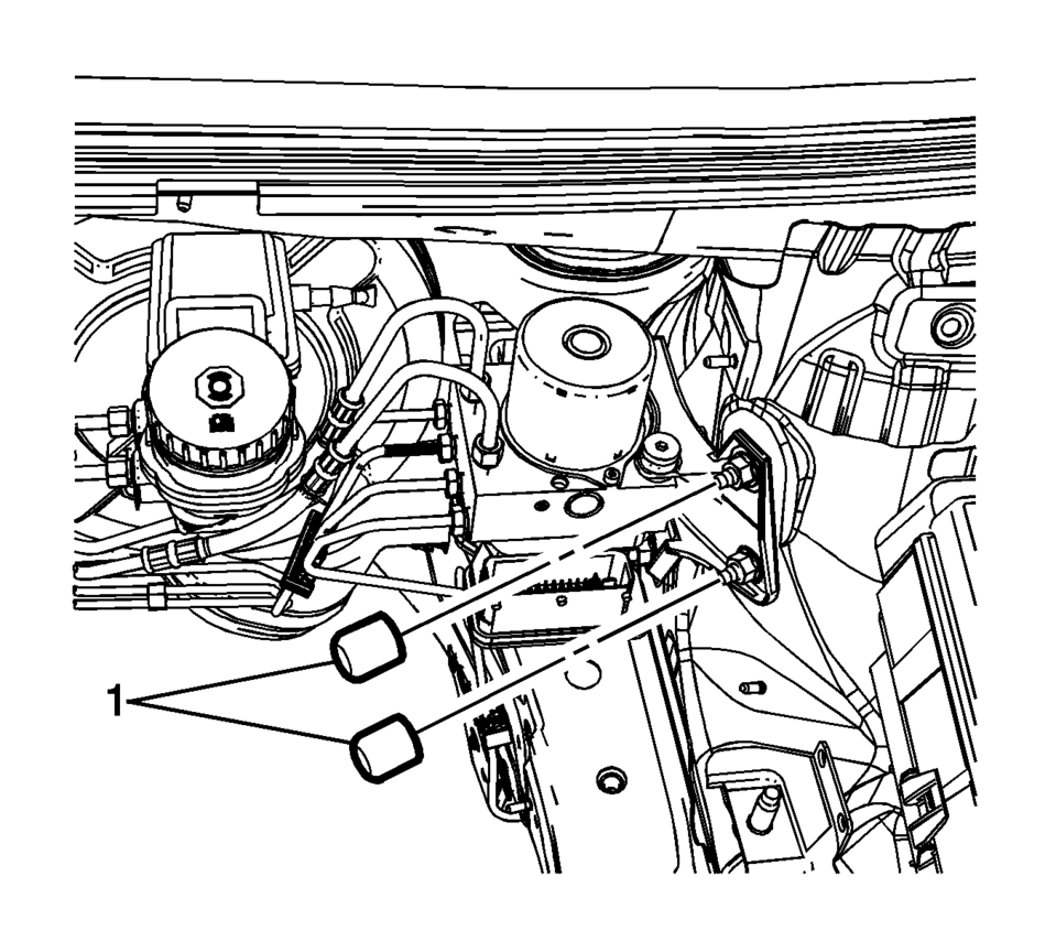
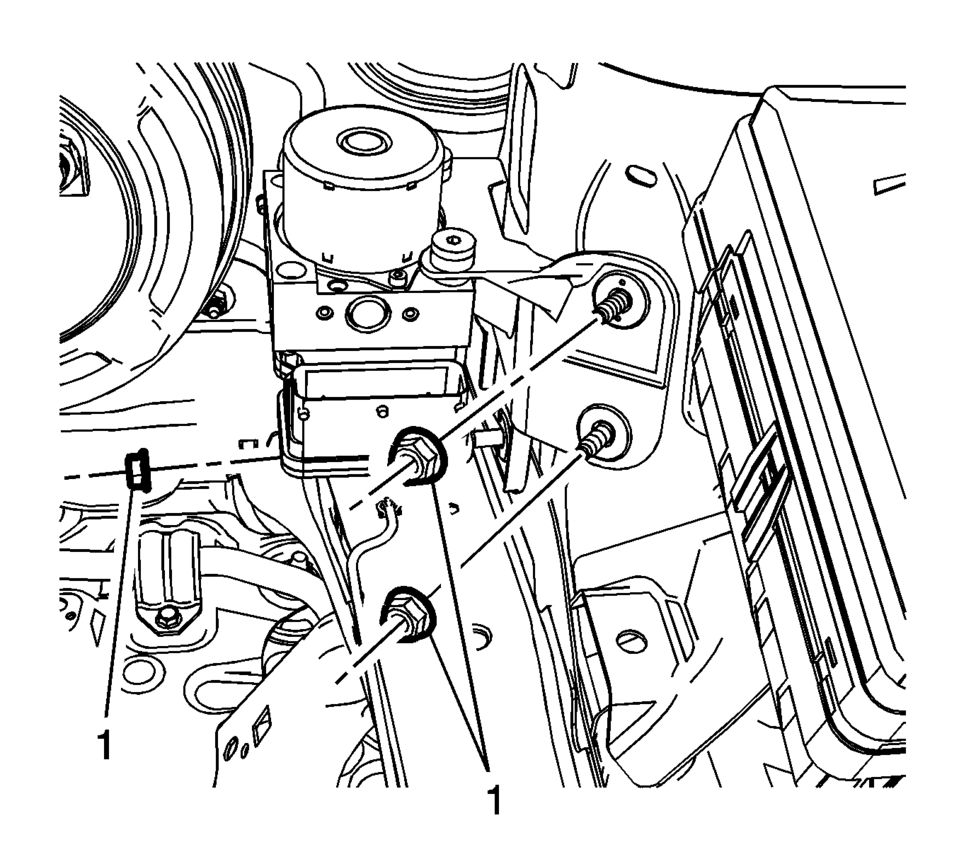
- Remove the protective caps (1) from the BPMV bracket nuts.
- Remove the EBCM/BPMV and bracket assembly nuts (1).
- Remove the EBCM/BPMV and bracket assembly from the vehicle.
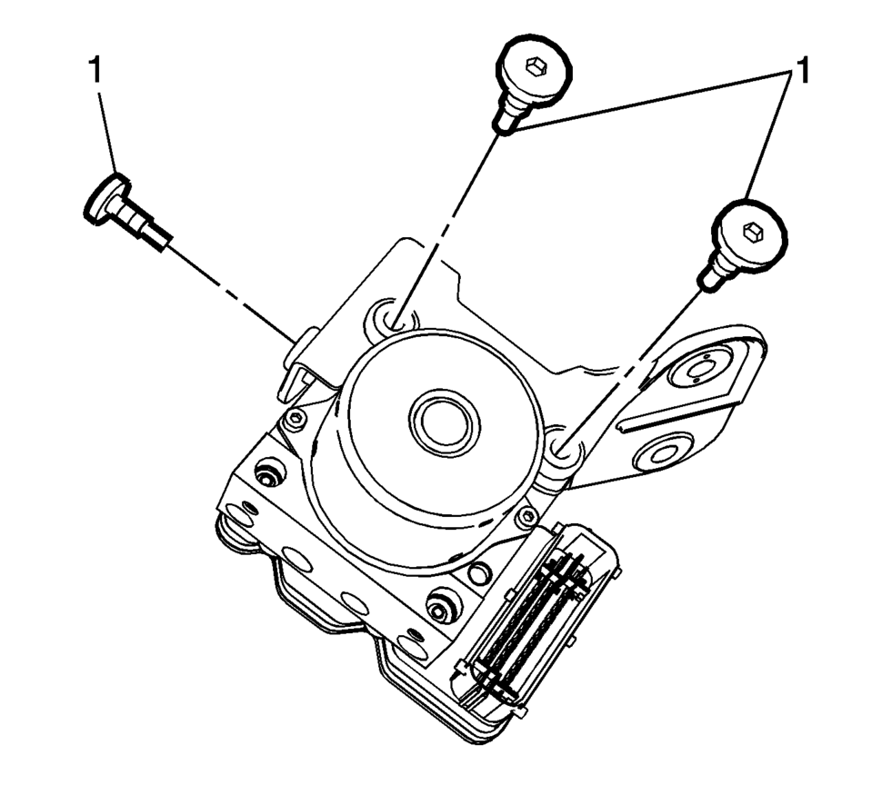
- Remove the BPMV bolts (1).
- Remove the BPMV bracket.
- If installing a new BPMV, remove the EBCM. Refer to Electronic Brake Control Module Replacement.
Note:
The area around the electronic brake control module (EBCM) and brake pressure modulator valve (BPMV) assembly must be free from loose dirt to prevent contamination of disassembled ABS components.
- Installation Procedure
-
- If installing a new BPMV, install the EBCM. Refer to Electronic Brake Control Module Replacement.
- Install the BPMV bracket to the BPMV.
- Install the BPMV bolts (1) and tighten to 11 Y (97 lb in)
.
- Install the EBCM/BPMV and bracket assembly to the vehicle.
- Install the EBCM/BPMV and bracket assembly nuts (1) and tighten to 17 Y
(12 lb ft)
.
- Install the protective caps (1) to the BPMV bracket nuts.
- Install the BPMV outlet brake pipe fittings (1) to the BPMV outlet ports.
- Connect the brake pipe fittings and tighten to 18 Y (13 lb ft)
.
- Connect the master cylinder primary brake pipe fitting (1) to the BPMV
and tighten to 18 Y (13 lb ft)
.
- Connect the master cylinder secondary brake pipe fitting (1) to the
BPMV and tighten to 18 Y (13 lb ft)
.
- Connect the EBCM electrical connector.
- Install the battery tray. Refer to Battery Tray Replacement.
- Bleed the hydraulic brake system. Refer to Hydraulic Brake System Bleeding.
- Perform the Diagnostic System Check - Vehicle.
- Observe the brake pedal feel after performing the diagnostic system check. If the pedal now feels spongy, air may have been in the secondary hydraulic circuit of the brake modulator which may have been introduced into the primary circuit. If the pedal feels spongy, bleed the antilock brake system. Refer to Antilock Brake System Automated Bleed.
Caution:
Refer to Fastener Caution.
Note:
Install the brake pipes in the same locations referenced during removal.
 Brake Pressure Modulator Valve Pipe Replacement
Removal Procedure
Warning: Refer to Brake Fluid Irritant Warning.
Caution: Refer to Brake Fluid Effects on Paint and Electrical
Components Caution.
Caution: Always ...
 Brake System External Leak Inspection
Warning: Refer to Brake Fluid Irritant Warning.
Caution: Refer to Brake Fluid Effects on Paint and Electrical Components
Caution.
In order to inspect for external brake fluid leaks ...
Other materials:
Front Wheel Drive Shaft Seal Replacement - Left Side
Special Tools
DT-446 Installer Drift
DT-7004 Slide Hammer
DT-23129 Universal Seal Remover
For equivalent regional tools, refer to Special Tools.
Removal Procedure
Raise and support the vehicle. Refer to Lifting and Jacking the Vehicle.
Remove the front suspension sk ...
Transmission Control Replacement
Removal Procedure
Remove the floor console. Refer to
Front Floor Console Replacement.
Lift both cable adjustment retainers (1), one for
each cable, to release the shift lever and selector lever cable.
.1
Pull the shift lever and selector lever cable ret ...
Engine Flywheel Installation
Special Tools
EN-652 Flywheel Holder
EN-45059 Torque Angle Sensor Kit
For equivalent regional tools, refer to Special Tools.
Clean the thread in the crankshaft.
Install the crankshaft position reluctor ring (1).
Install the flywheel (2).
Install the EN-6 ...

0.0054