Chevrolet Sonic Repair Manual: Electronic Component Description
- Control Solenoid Valve Assembly
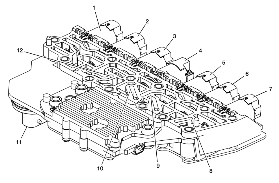
(1) Pressure Control Solenoid 3 (R-1/4-5-6) (2) (GEN 1) Pressure Control Solenoid 2 (3-5-R) (2) (GEN 2) Pressure Control Solenoid 5 (1-2-3-4) (3) Torque Converter Clutch (TCC) Pressure Control Solenoid (4) Shift Solenoid 1 (On/Off) (5) (GEN 1) Pressure Control Solenoid 5 (1-2-3-4) (5) (GEN 2) Pressure Control Solenoid 2 (3-5-R) (6) Pressure Control Solenoid 4 (2-6) (7) Line Pressure Control Solenoid (8) (GEN 1) Transmission Fluid Pressure (TFP) Switch 1 (3-5-R) (9) (GEN 1) Transmission Fluid Pressure (TFP) Switch 3 (2-6) (10) (GEN 1) Transmission Fluid Pressure (TFP) Switch 4 (1-2-3-4) (11) Pass Through Connector (12) (GEN 1) Transmission Fluid Pressure (TFP) Switch 5 (4-5-6/R-1)
The control solenoid (w/body and TCM) valve assembly contains the following components:
- Transmission control module (TCM)
- Clutch pressure control solenoids (Clutch PC Sol)
- Shift solenoids (SS)
- Line pressure control solenoid (Line PC Sol)
- Torque converter clutch pressure control solenoid (TCC PC Sol)
- Transmission fluid temperature sensor (TFT Sensor)
- TCM temperature sensor
- Power-up temperature sensor
- Transmission fluid pressure switches (TFP Sw)
These components are not serviced separately. The control solenoid (w/body and TCM) valve assembly utilizes a lead-frame system to connect these components electrically to the TCM. No wires are used for these components. The control solenoid (w/body and TCM) valve assembly bolts directly to the lower and upper valve body assemblies inside the transmission. The control solenoid (w/body and TCM) valve assembly connects to the engine harness 14-way connector.
- Manual Shift Detent Lever with Shaft Position Switch Assembly
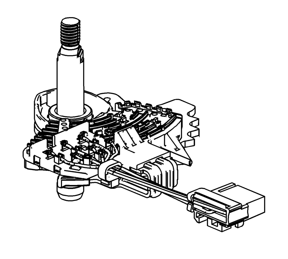
The transmission shaft position switch assembly is a sliding contact switch attached to the manual shaft detent lever assembly inside the transmission case. The five inputs to the TCM from the transmission manual shift shaft switch assembly indicate the transmission gear selector lever position. This information is used for engine controls as well as determining the transmission shift patterns. The state of each input is available for display on the scan tool. The five input parameters represented are Signal A, Signal B, Signal C, Signal P (Parity) and Signal N (P/N Start).
- Input Speed Sensor (ISS)
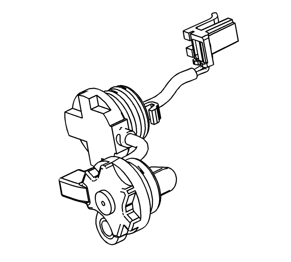
The input speed sensor (ISS) is a hall-effect type sensor. The ISS mounts to the transmission case assembly and connects to the control solenoid (w/body and TCM) valve assembly through a wire harness and connector. The sensor faces the 3-5-R clutch piston housing machined teeth surface. The sensor receives 8.3?.3 volts on the ISS/OSS Supply Voltage circuit from the TCM. As the 3-5-R/4-5-6 clutch piston housing rotates, the sensor produces a signal frequency based on the machined surface of the 3-5-R/4-5-6 clutch piston housing. This signal is transmitted through the ISS signal circuit to the control solenoid (w/body and TCM) valve assembly. The TCM uses the ISS signal to determine line pressure, transmission shift patterns, torque converter clutch (TCC) slip speed and gear ratio.
- Output Speed Sensor (OSS)
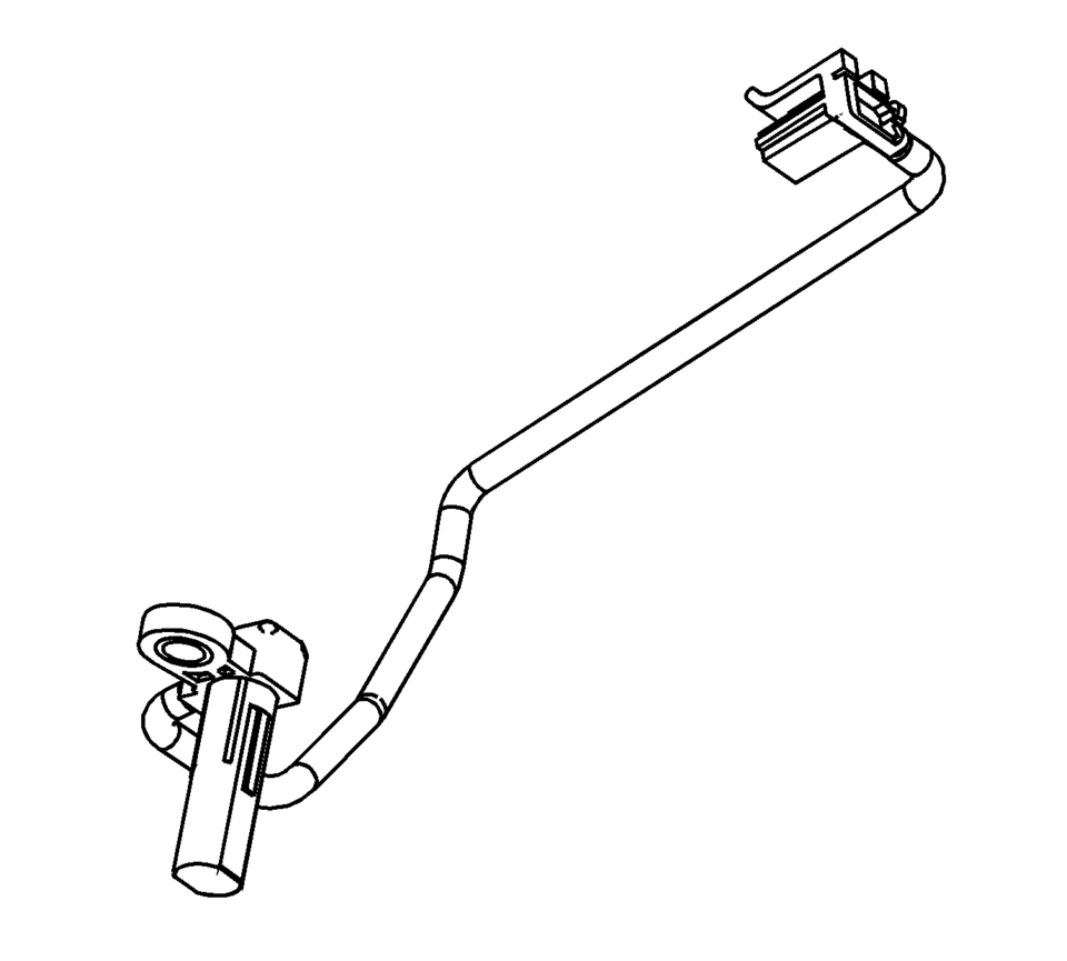
The output speed sensor (OSS) is a hall-effect type sensor. The OSS mounts to the transmission case below the control valve body assembly and connects to the control solenoid (w/body and TCM) valve assembly through a wire harness and connector. The sensor faces the Park gear machined teeth surface. The sensor receives 8.3?.3 volts on the ISS/OSS supply voltage circuit from the TCM. As the front differential transfer drive gear assembly rotates, the sensor produces a signal frequency based on the machined surface of the Park gear. This signal is transmitted through the OSS signal circuit to the TCM. The TCM uses the OSS signal to determine line pressure, transmission shift patterns, torque converter clutch (TCC) slip speed and gear ratio.
 Drive and Driven Sprocket, Drive Link, and Park Pawl Removal (6T40/45/50)
Drive and Driven Sprocket, Drive Link, and Park Pawl Removal
Callout
Component Name
1
Drive Link Lube Scoop
...
 Engine Replacement (Automatic Transmission)
Special Tools
J-45859 Wheel Drive Shaft Remover
CH-807 Closure Plugs
For equivalent regional tools, refer to Special Tools.
Removal Procedure
Remove the battery and battery tr ...
Other materials:
Brake Rotor Refinishing
Special Tools
CH-41013 Rotor Resurfacing Kit
CH-42450-A Wheel Hub Resurfacing Kit
For equivalent regional tools, refer to Special Tools.
Warning: Refer to Brake Dust Warning.
Note:
The disc brake rotors do not require refinishing as part of routine
brake system servic ...
Air Cleaner Assembly Replacement
Air Cleaner Assembly Replacement
Callout
Component Name
1
Air Cleaner Outlet Duct Clamp.
Procedure
Loosen clamp and remove air cleaner outlet duct from air cleaner assembly.
2
Mass ...
Hood
1. To open the hood of the Nissan Armada, pull the hood release handle 1 located
beneath the driver’s side instrument panel. This action will cause the hood to pop
up slightly.
2. Move to the front of the Nissan Armada and locate the secondary safety lever
2. Slide it sideways with your ...

0.0104