Chevrolet Sonic Repair Manual: Engine Replacement (Automatic Transmission)
Special Tools
- J-45859 Wheel Drive Shaft Remover
- CH-807 Closure Plugs
For equivalent regional tools, refer to Special Tools.
- Removal Procedure
-
- Remove the battery and battery tray. Refer to Battery Tray Replacement.
- Relieve the fuel system pressure. Refer to Fuel Pressure Relief.
- Recover the refrigerant. Refer to Refrigerant Recovery and Recharging.
- Remove the front tire and wheel assembly. Refer to Tire and Wheel Removal and Installation.
- Remove the front bumper fascia. Refer to Front Bumper Fascia Replacement.
- Remove the front wheelhouse liner inner front extensions. Refer to Front Wheelhouse Liner Inner Front Extension Replacement.
- Drain the cooling system. Refer to Cooling System Draining and Filling.
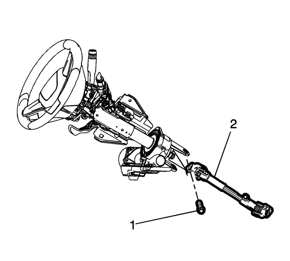
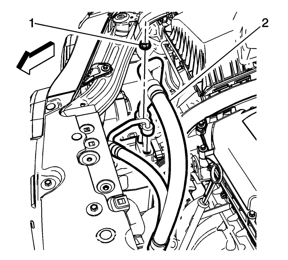
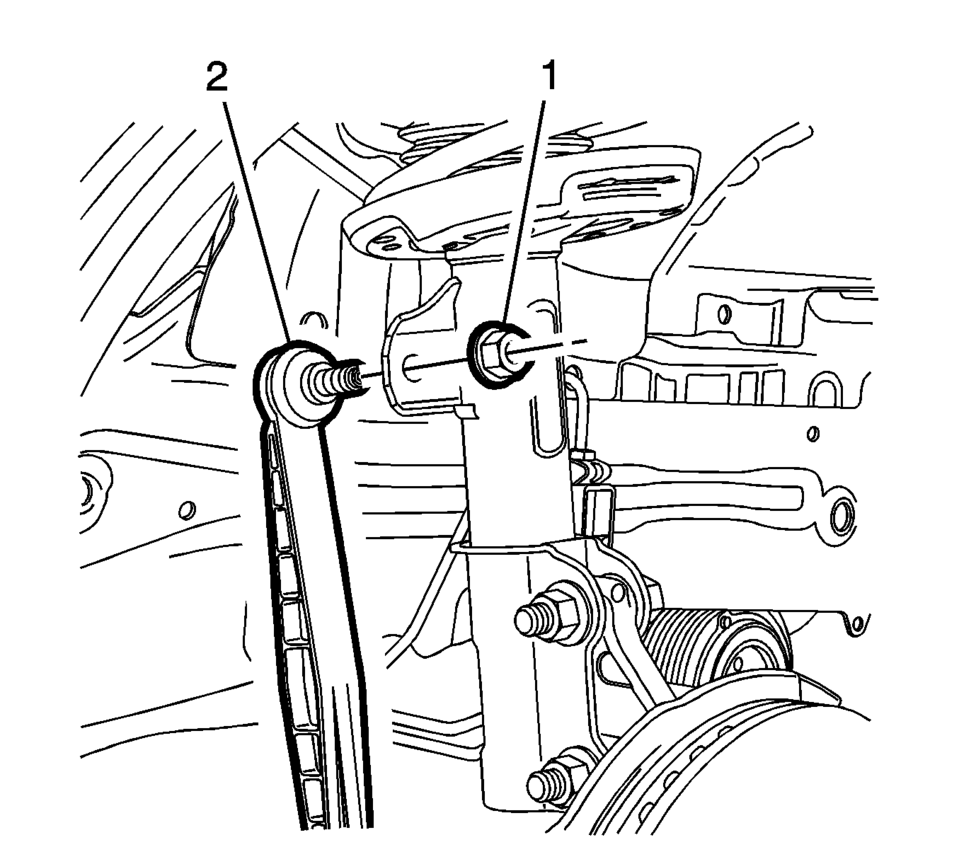
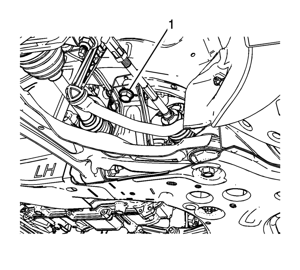
- Remove the lower intermediate steering shaft bolt (1) and slide the shaft away from steering column. Refer to Intermediate Steering Shaft Replacement.
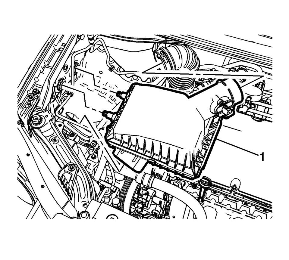
- Remove the air cleaner assembly (1). Refer to Air Cleaner Assembly Replacement.
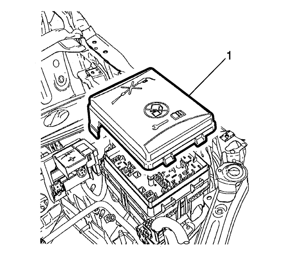
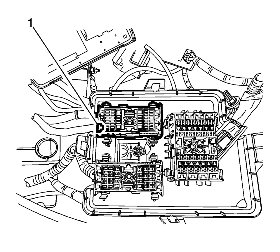
- Remove the junction block cover (1).
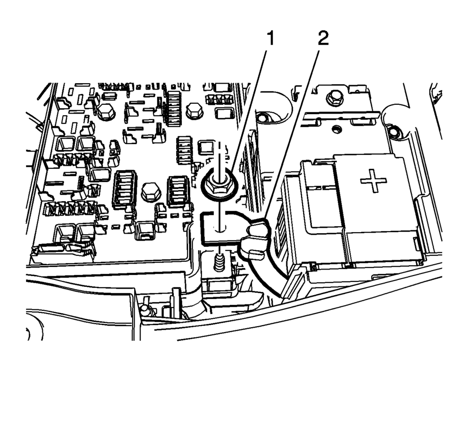
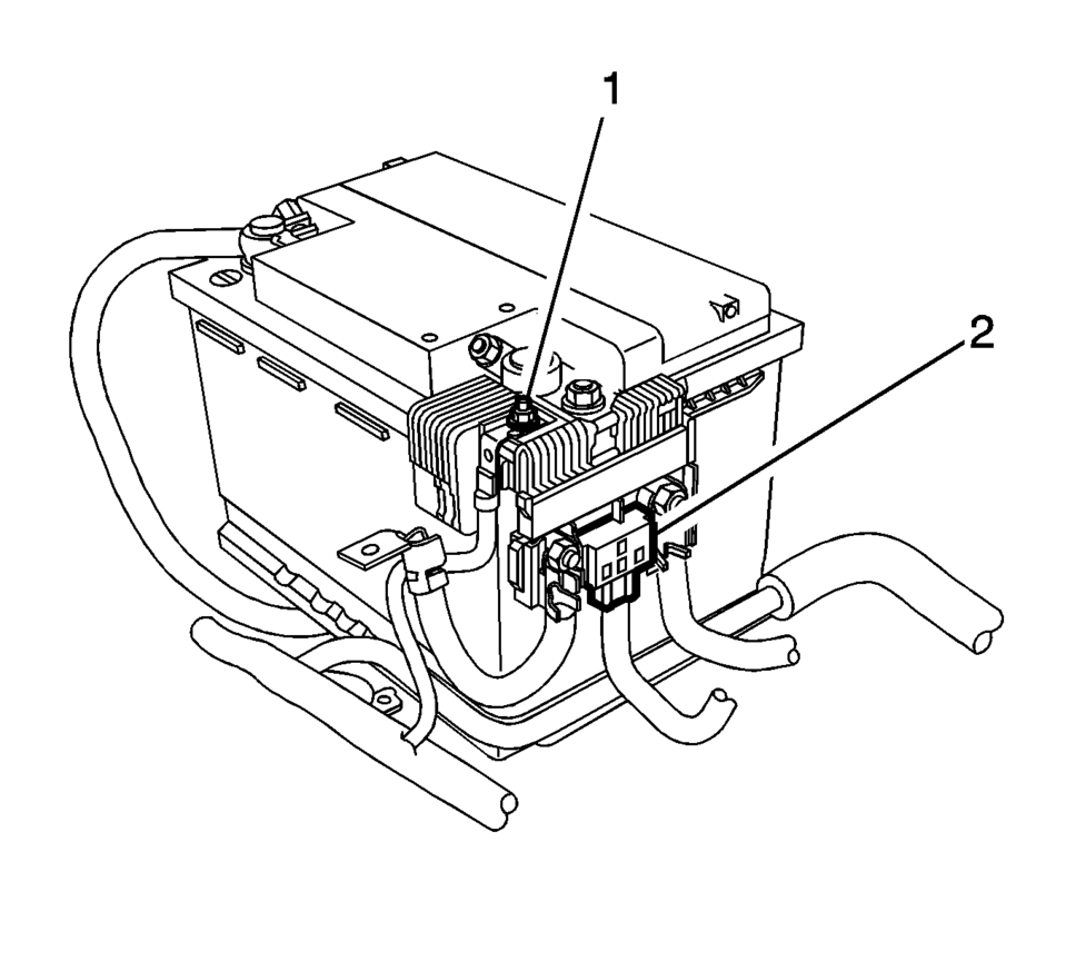
- Remove the positive battery cable nut (1) from the junction block.
- Remove the positive battery cable (2) from the junction block.
- Remove the positive cable nut (1) and battery positive cable, from the battery positive cable junction block.
- Disconnect the body wiring master harness connector (2), from the battery positive cable junction block.
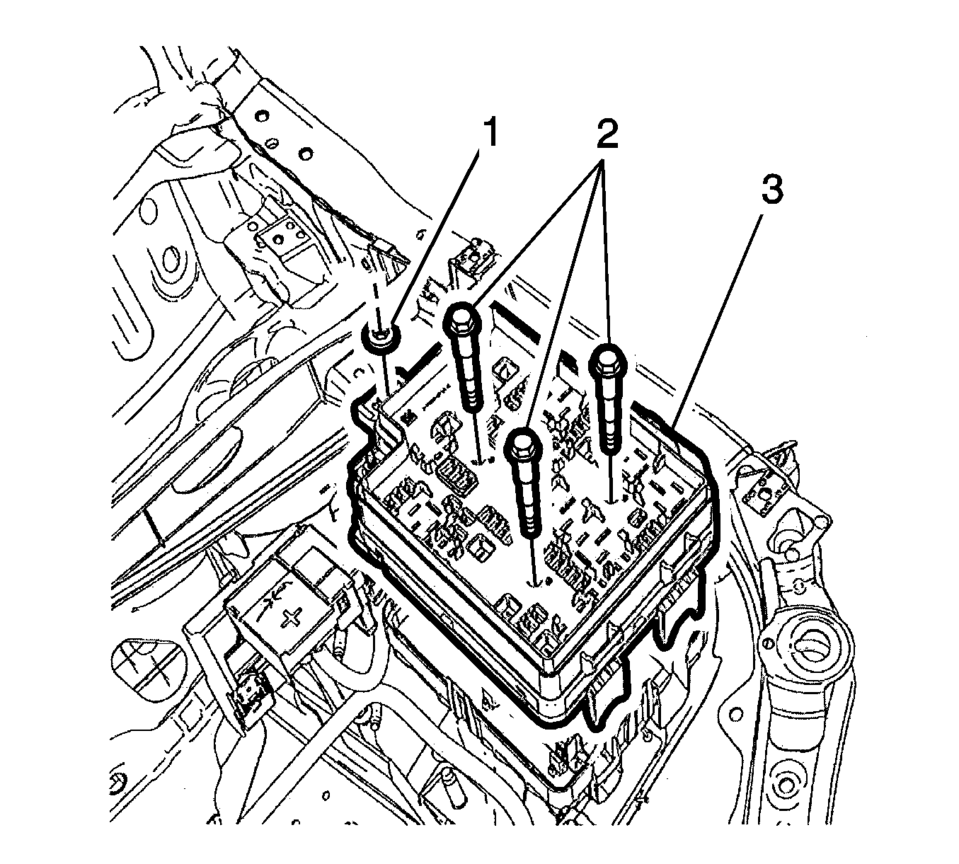
- Remove the junction block nut (1).
- Remove the junction block bolts (2).
- Disconnect the wiring harness from the junction block base.
- Remove the junction block (3) from the base.
- Disconnect the wiring harness plug from the front compartment fuse block.
- Reposition the wiring harness (1) on top of the engine.
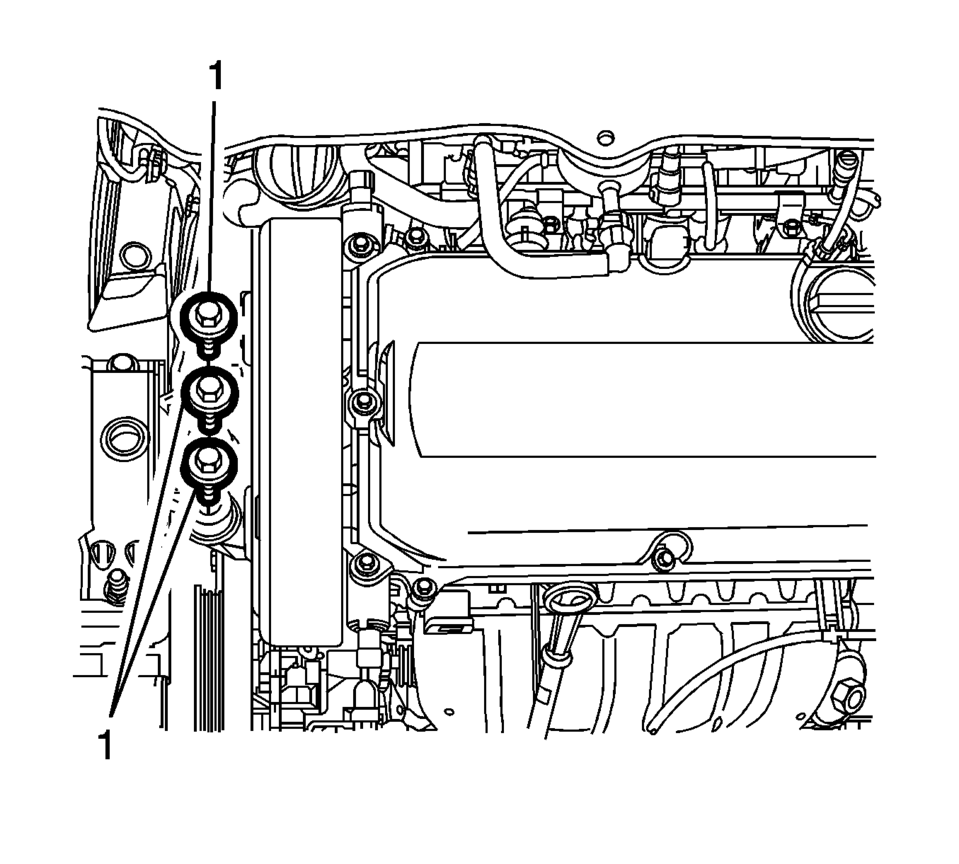
- Remove the ground nuts (1) and reposition the wiring harness (2) aside.
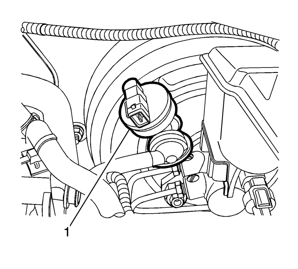
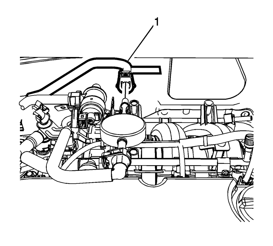
- If equipped with electrical vacuum pump, disconnect the electrical connector and remove the brake booster hose (1).
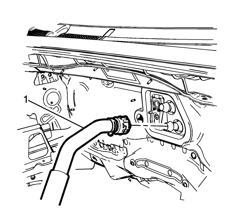
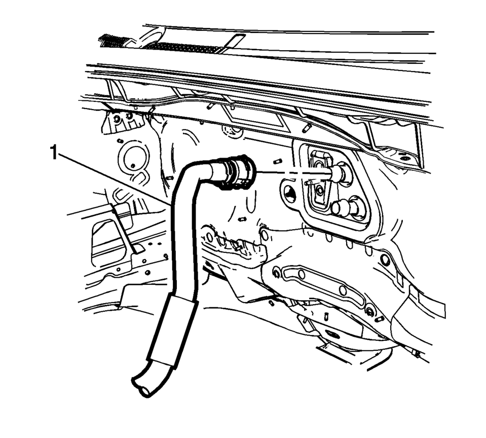
- Disconnect the heater inlet hose (1) from the heater core. Refer to Heater Inlet Hose Replacement.
- Disconnect the heater outlet hose (1) from the heater core. Refer to Heater Outlet Hose Replacement.
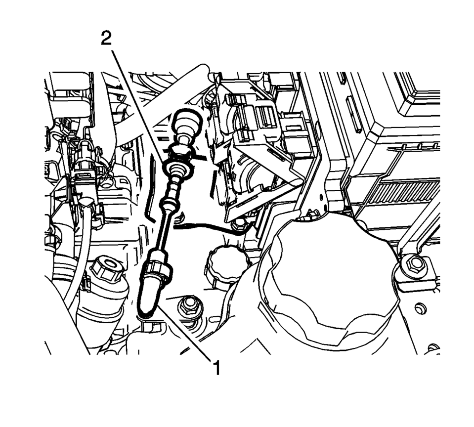
- Disconnect the transmission range selector lever cable terminal (1) from the transmission manual shift lever pin.
- Remove the transmission range selector lever cable (2) from the cable bracket.
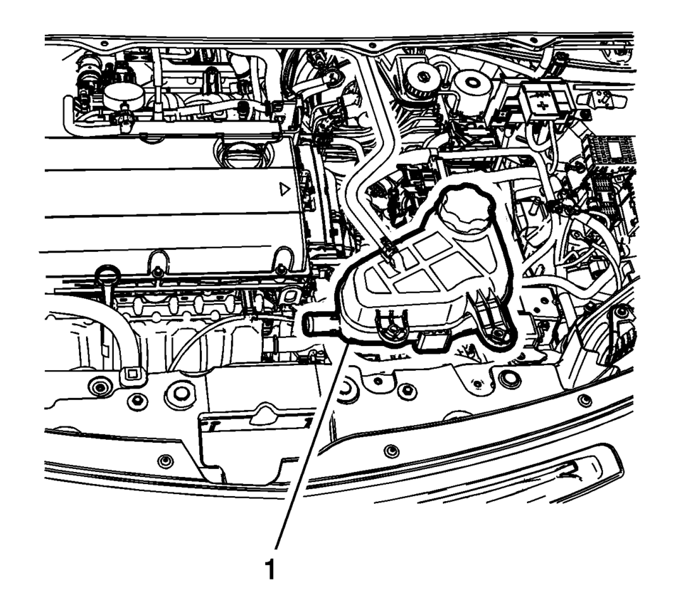
- Remove the radiator surge tank (1) and position aside. Refer to Radiator Surge Tank Replacement.
- Disconnect the fan connector.
- Remove air conditioning compressor and condenser hose nut (1).
- Remove air conditioning compressor and condenser hose (2) from refrigerant hose.
- Disconnect the fuel feed pipe (1). Refer to Plastic Collar Quick Connect Fitting Service.
- Install and close the fuel feed pipe with CH-807 plug.
- Disconnect the engine coolant sensor from radiator.
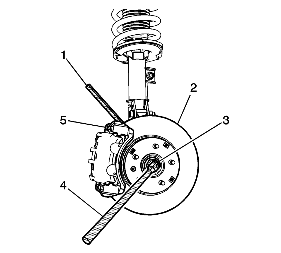
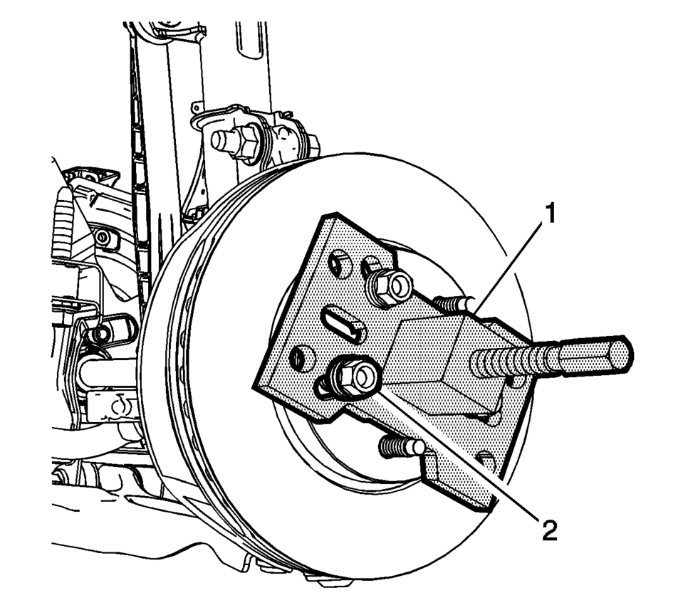
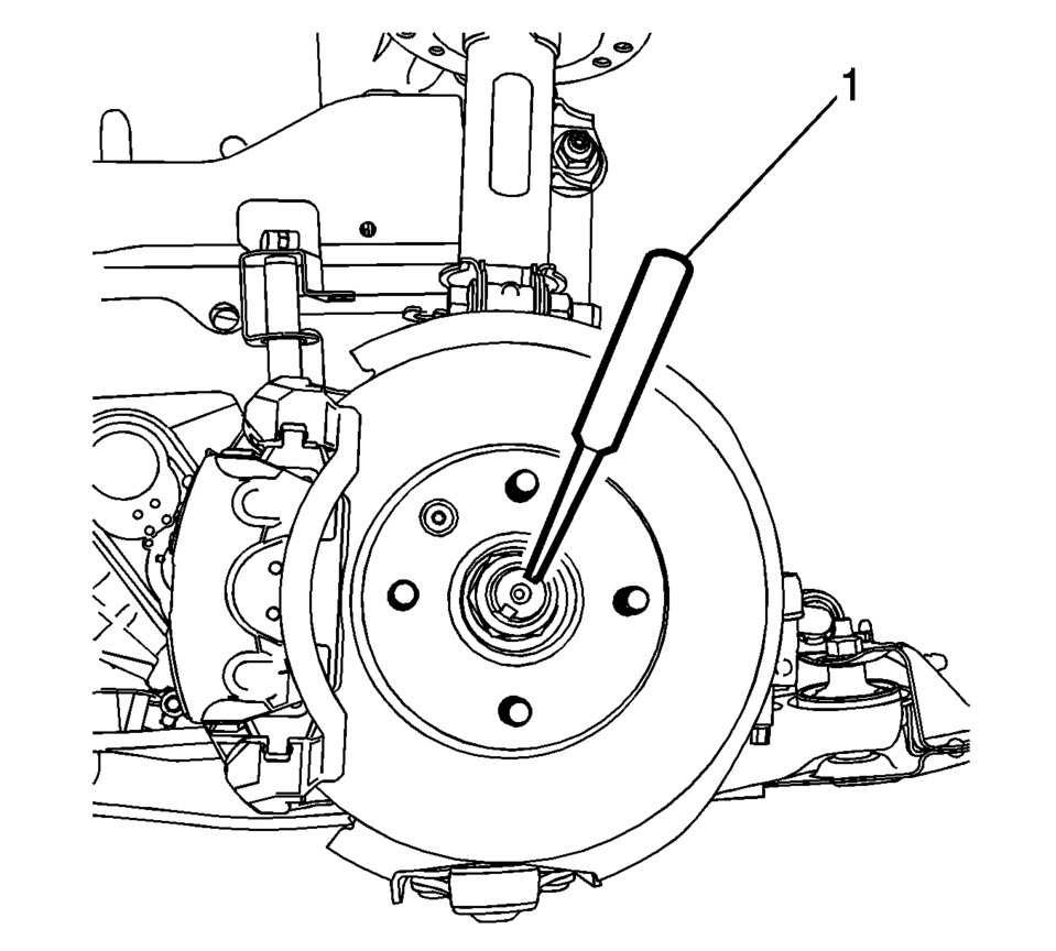
- Insert a brass drift or punch (1) in the cooling fins of the front brake rotor (2).
- Rotate the brake rotor until it comes in contact with the brake caliper mount bracket (5).
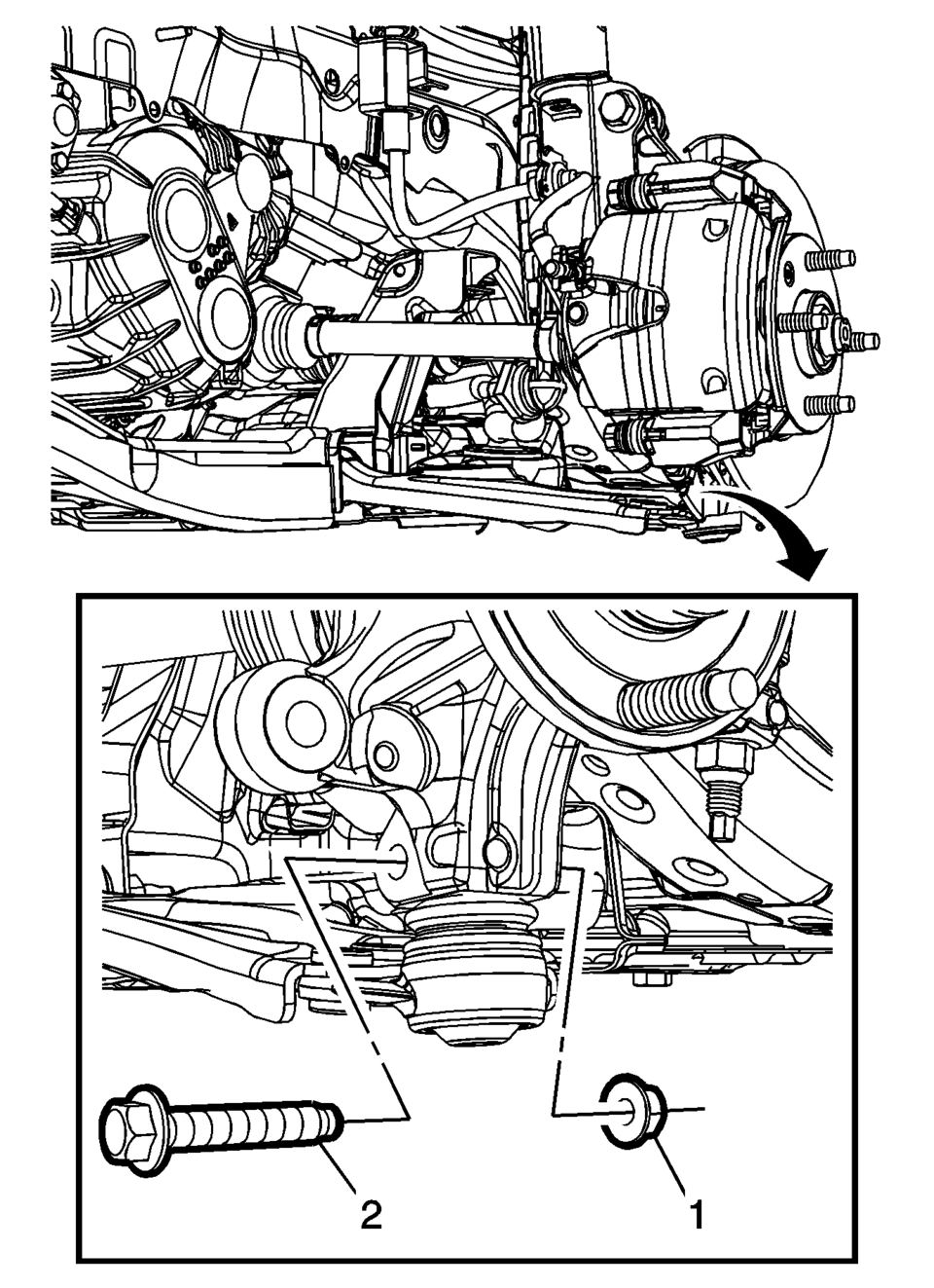
- Use a suitable tool to release the crimping on the wheel drive shaft retaining nut.
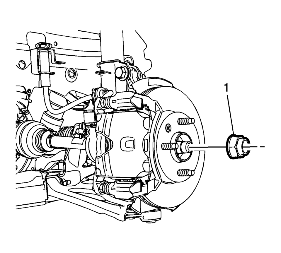
- The wheel drive shaft retaining nut (1) must be discarded after removal.
- Remove and discard the wheel drive shaft nut (1).
- Remove the upper stabilizer shaft link nut (1).
- Disconnect the stabilizer shaft link (2).
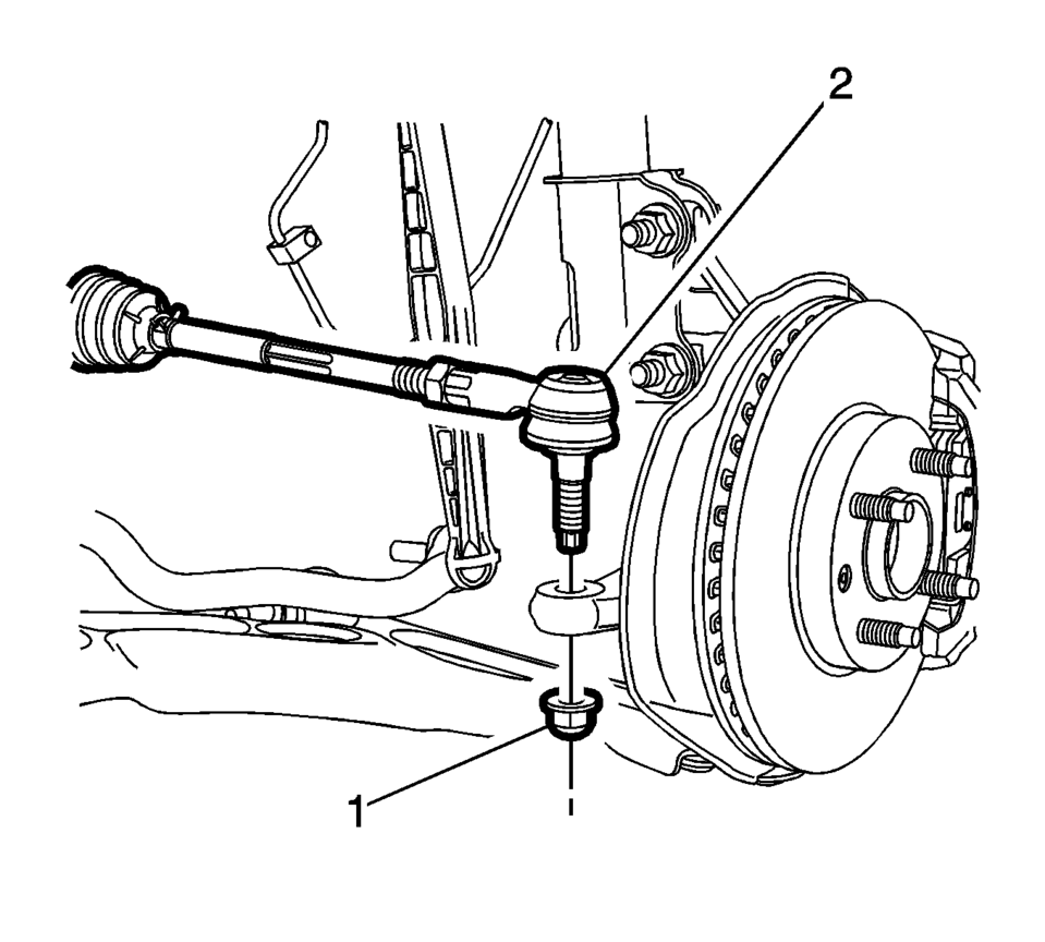
- Remove and DISCARD the steering linkage outer tie rod nut (1).
- Separate the steering linkage outer tie rod (2) from the steering knuckle. Steering Linkage Outer Tie Rod Replacement.
- Separate the control arm ball joint from the steering knuckle. Refer to Lower Control Arm Replacement.
- Using the J-45859 wheel drive shaft remover (2), separate the wheel drive shaft from the steering knuckle (1).
- Remove the upper stabilizer shaft link from the absorber on both sides. Refer to Stabilizer Shaft Link Replacement.
- Remove the front exhaust pipe. Refer to Exhaust Front Pipe Replacement.
- Remove the lower oil pan to transmission lower bolts (1).
- Remove the lower oil pan to transmission lower bolts (1) and nut (2).
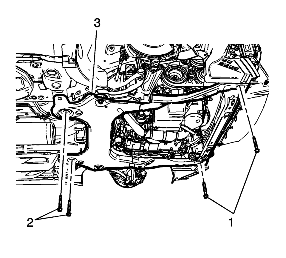
- Remove the frame braces.
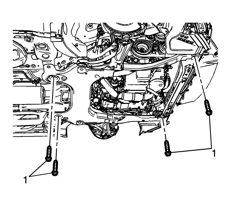
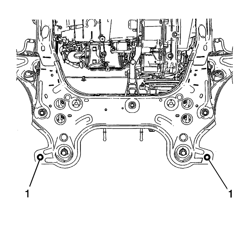
- Remove the frame front bolts (1).
- Position an engine support table under the powertrain assembly.
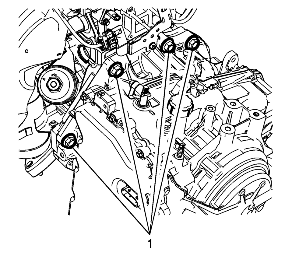
- Remove the upper frame suspension retaining bolts (1) on both sides.
- Mark the location of the right engine mount bolts (1) before removing.
- Remove and Discard the right side engine mount bolts (1). Refer to Engine Mount Replacement.
- Mark the location of the transmission mount bolts (1) before removing.
- Remove and DISCARD the transmission mount bolts (1) ?Eleft side. Refer to Transmission Mount Replacement - Left Side.
- Disconnect any additional electrical connections as necessary.
- Raise the vehicle until the powertrain is clear for removal.
- Remove the starter. Refer to Starter Replacement.
- Remove the torque converter bolt access plug next to the starter opening.
- Remove the torque converter bolts.
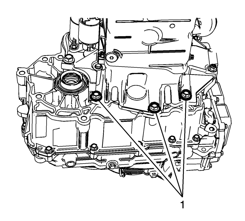
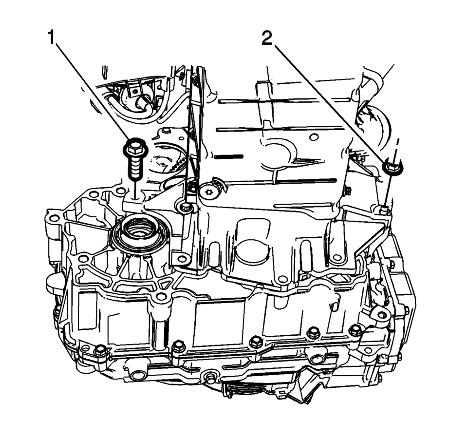
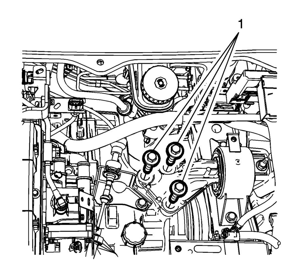
- Remove the upper transmission to engine bolts (1) and separate the engine and transmission.
- Disconnect any electrical connectors as needed.
- Install the engine to the engine stand.
- Transfer parts as needed.

.-
Note:
Perform steps 33 through 41 to both sides.
Note:
Note:
Reverse the wheel lug nuts and washers so the flat part of the wheel nut is facing the washers.
Note:
Blocks of wood can be used between the front of the frame and the oil pan to table in order to level the powertrain during the removal.
- Installation Procedure
-
- Remove the engine from the engine stand.
- Install the transmission to the engine.
- Install the upper transmission to engine bolts (1) and tighten to
60 Y (44 lb ft)
.
- Place the powertrain into the front frame.
- Slowly lower the body onto the powertrain.
- Install the NEW left transmission mount to transmission bolts (1) and
tighten to 50 Y (37 lb ft) plus 70 degrees
.
- Install the NEW right side engine mount bolts (1) and tighten to
50 Y (37 lb ft) plus 70 degrees
.
- Perform Powertrain Mount Balancing.
- Align the frame and body through alignment hole (1).
- Install the frame (3) rear bolts (2) and tighten to 135 Y (100 lb ft)
.
- Install the frame (3) front bolts (1) and tighten to 58 Y (43 lb ft)
.
- Install the upper frame suspension retaining bolts (1) on both sides
and tighten to 135 Y (100 lb ft)
.
- Remove the lift table.
- Install the lower oil pan to transmission bolts (1) and tighten to
40 Y (30 lb ft)
.
- Install the lower oil pan to transmission lower bolts (1) and tighten
to 60 Y (44 lb ft)
.
- Install the lower oil pan to transmission lower and nut (2) and tighten
to 40 Y (30 lb ft)
.
- Install NEW flex plate to torque converter bolts and tighten to 60 Y
(44 lb ft)
.
- Install the starter. Refer to Starter Replacement.
- Install the front exhaust pipe. Refer to Exhaust Front Pipe Replacement.
- Inset the wheel drive shaft to the steering knuckle.
- Install the NEW steering linkage outer tie rod nut (1) and tighten to
30 Y (22 lb ft) Plus 128 degrees
.
- Install the steering linkage outer tie rod to the steering knuckle. Refer to Steering Linkage Outer Tie Rod Replacement.
- Install the control arm ball joint to the steering knuckle. Refer to Lower Control Arm Replacement.
- Connect the stabilizer shaft link (2).
- Install the upper stabilizer shaft link nut (1) and tighten to 65 Y
(48 lb ft)
.
- Insert a brass drift or punch (1) in the cooling fins of the front brake rotor (2).
- Rotate the brake rotor until it comes in contact with the brake caliper mount bracket (5).
- Install the NEW wheel drive shaft nut (1) and tighten to 250 Y (184 lb ft)
.
- Using a punch (1), stake the wheel drive shaft nut.
- Remove the CH-807 plug.
- Connect the fuel feed pipe (1). Refer to Plastic Collar Quick Connect Fitting Service.
- Connect the engine coolant sensor from radiator.
- Install air conditioning compressor and condenser hose to the refrigerant hose.
- Install air conditioning compressor and condenser hose nut (1) tighten
nut to 22 Y (16 lb ft)
.
- Install the radiator surge tank (1). Refer to Radiator Surge Tank Replacement.
- Connect the fan connector.
- Install the transmission range selector lever cable (2) to the cable bracket.
- Connect the transmission range selector lever cable terminal (1) to the transmission manual shift lever pin.
- Adjust the automatic transmission range selector lever cable. Refer to Range Selector Lever Cable Adjustment.
- Connect the heater inlet hose to the heater core (1). Refer to Heater Inlet Hose Replacement.
- Connect the heater outlet hose to the heater core (1). Refer to Heater Outlet Hose Replacement.
- If equipped with electrical vacuum pump, connect the electrical connector and install the brake booster hose (1).
- Install the ground nuts (1) and reposition the wiring harness (2).
- Clip in the wiring harness plugs (1).
- Install the junction block to the base.
- Install the junction block bolts (2) and tighten to 5 Y (44 lb in)
.
- Install the junction block nut (1) and tighten to 5 Y (44 lb in)
.
- Install the battery positive cable to the battery positive cable junction
block and tighten nut (1) to 5 Y (44 lb in)
.
- Connect the body wiring master harness connector (2), to the battery positive cable junction block.
- Position the positive battery cable to the junction block.
- Install the positive battery cable nut (2) and tighten to 7 Y (62 lb in)
.
- Install the junction block cover (1).
- Install the air cleaner assembly (1). Refer to Air Cleaner Assembly Replacement.
- Install the lower intermediate steering shaft bolt (1). Refer to Intermediate Steering Shaft Replacement.
- Install the battery and battery tray. Refer to Battery Tray Replacement.
- Install the front tire and wheel assembly. Refer to Tire and Wheel Removal and Installation.
- Install the front bumper fascia. Refer to Front Bumper Fascia Replacement.
- Install the front wheelhouse liner inner front extensions. Refer to Front Wheelhouse Liner Inner Front Extension Replacement.
- Evacuate and charge the refrigerant system. Refer to Refrigerant Recovery and Recharging.
- Fill the cooling system. Refer to Cooling System Draining and Filling.
Caution:
Refer to Fastener Caution.
Caution:
Refer to Torque-to-Yield Fastener Caution.
Caution:
Refer to Torque-to-Yield Fastener Caution.
Note:
Perform steps 20 through 29 to both sides.
Caution:
Refer to Torque-to-Yield Fastener Caution.
.-
 Engine Replacement
Special Tools
EN-48244 Engine Assembly Remove/Install Pallet Supporter
Removal Procedure
Remove the battery and battery tray. Refer to Battery Tray Replacement.
Relieve the fue ...
 Engine Replacement (Manual Transmission)
Special Tools
J-45859 Wheel Drive Shaft Remover .
CH-807 Closure Plugs .
For equivalent regional tools, refer to Special Tools.
Removal Procedure
Remove the battery and b ...
Other materials:
Hood Adjustment
Hood Adjustment
Callout
Component Name
1
Hood
Caution: Refer to Fastener Caution.
Procedure
Loosen the 4 hood hinge nuts.
Adjust the hood in order to obtain an even gap on both sides between
...
Battery Charging
Special Tools
EL 50313 Battery Tester
For equivalent regional tools, refer to Special Tools.
Diagnostic Aids
For best results, use an automatic taper-rate battery charger with a
voltage capability of 16 V.
The charging area should be well ventilated.
Do not charge a bat ...
Radiator Outlet Hose Replacement (LDE LUW)
Special Tools
BO-38185 Hose Clamp Pliers
For equivalent regional tools, Refer to Special Tools.
Removal Procedure
Drain the cooling system. Refer to Cooling System Draining and Filling.
Remove the radiator outlet hose clamp (1) at the engine using BO-38185 ...

0.0081