Chevrolet Sonic Repair Manual: Front End Upper Tie Bar Replacement
- Removal Procedure
-
- Disable the SIR System. Refer to SIR Disabling and Enabling.
- Disconnect the negative battery cable. Refer to Battery Negative Cable Disconnection and Connection.
- Remove all related panels and components.
- Visually inspect the damage. Repair as much of the damage as possible.
- Remove the sealers and anti-corrosion materials from the repair area, as necessary. Refer to Anti-Corrosion Treatment and Repair.
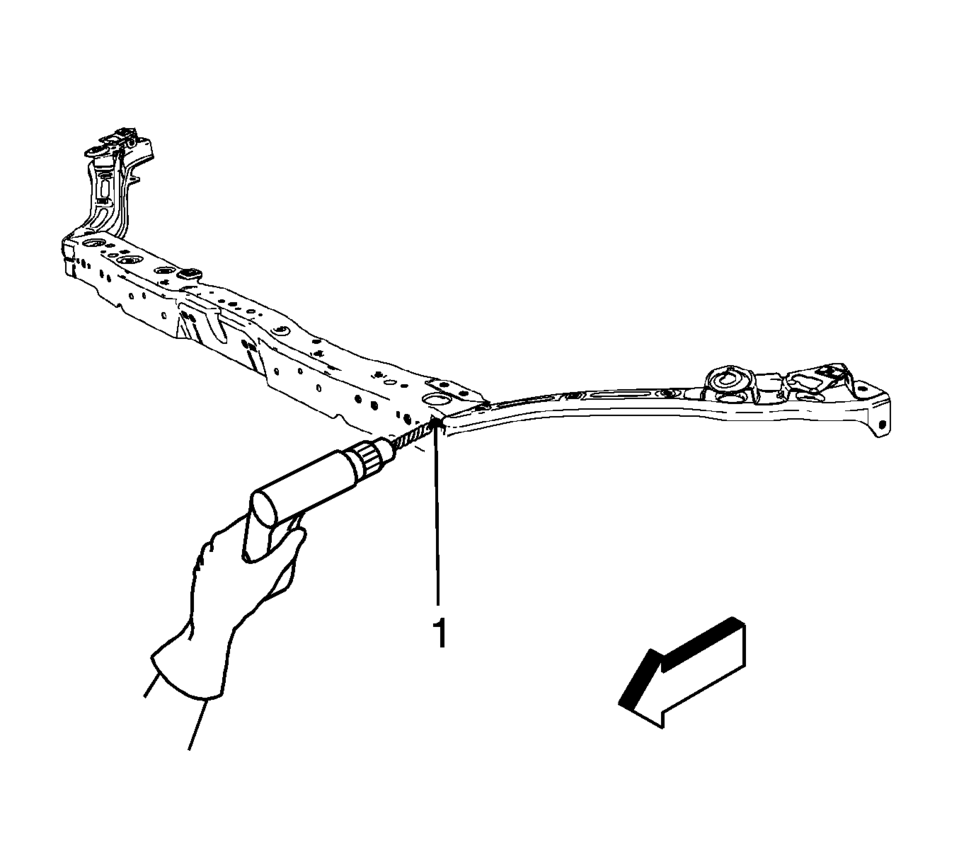
- Locate and mark all the necessary factory welds of the front upper tie bar assembly.
- Drill all factory welds. Note the number and location of welds for installation of the service assembly.
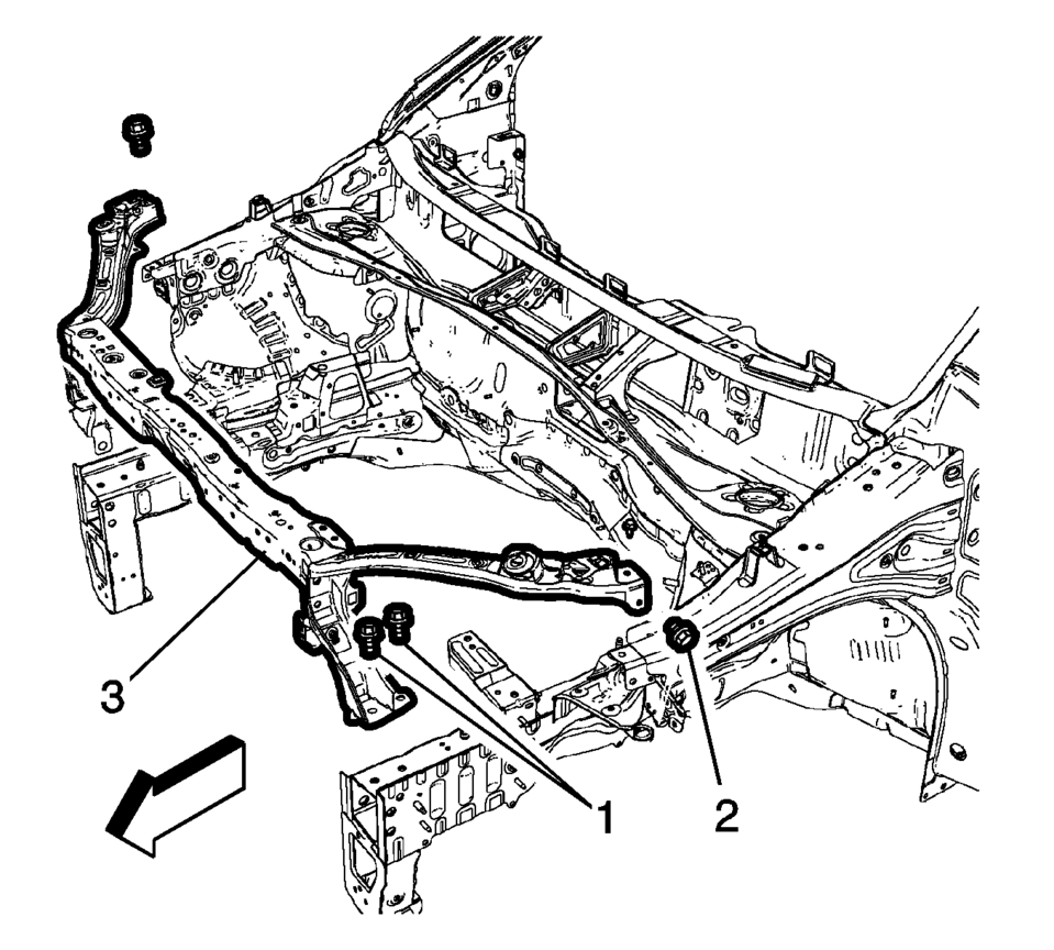
- Remove the front end upper tie bar support bolts (1) and front end upper tie bar bolts (2).
- Remove the front end upper tie bar assembly (3).
Warning:
Refer to Approved Equipment for Collision Repair Warning.
Warning:
Refer to Glass and Sheet Metal Handling Warning.
- Installation Procedure
-
- Drill 8 mm (5/16 in) plug weld holes as necessary on service parts, in the locations noted from the original assembly (1).
- Clean and prepare the mating surface for welding, as necessary.
- Position the front upper tie bar support (1) and front upper tie bar (2) on the vehicle
- Verify the fit of the front end upper tie bar.
- Install the front upper tie bar support bolts (3) and tighten to
22 Y (16 lb ft)
.
- Install the front upper tie bar bolts (4) and tighten to 9 Y (80 lb in)
.
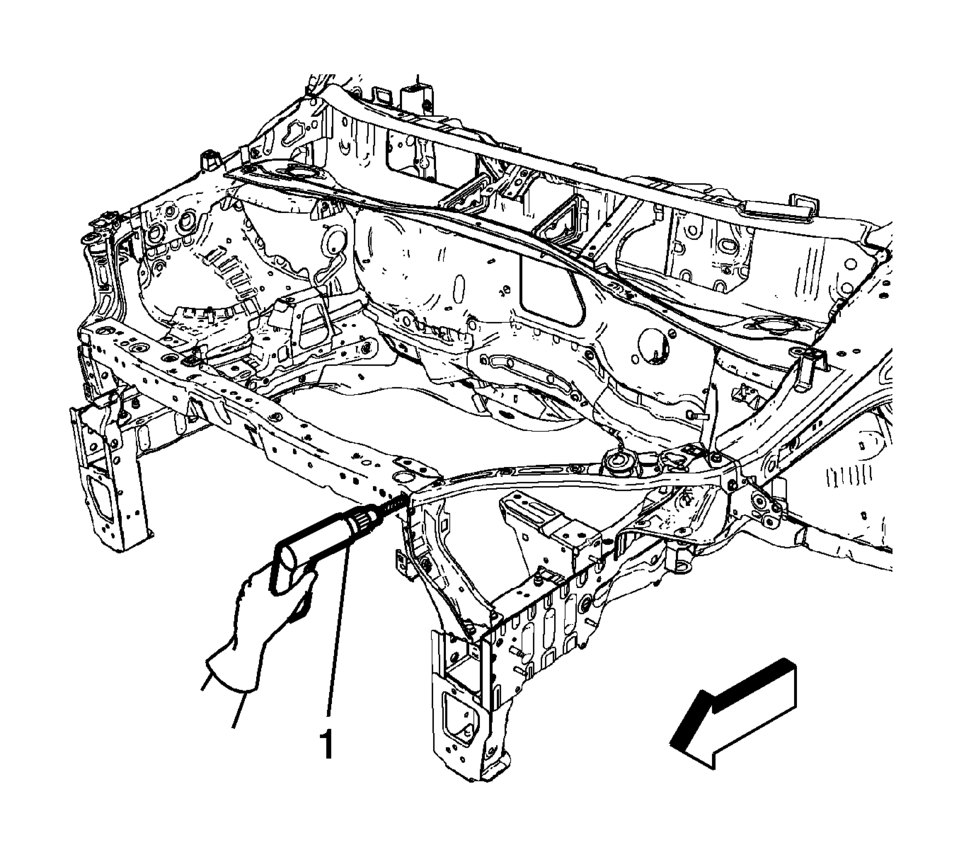
- When the service assembly is correctly positioned, plug weld accordingly (1).
- Measure frequently to ensure proper fit and alignment.
- Clean and prepare all welded surfaces.
- Apply the sealers and anti-corrosion materials to the repair area, as necessary. Refer to Anti-Corrosion Treatment and Repair.
- Paint the repaired area. Refer to Basecoat/Clearcoat Paint Systems.
- Install all related panels and components.
- Connect the negative battery cable. Refer to Battery Negative Cable Disconnection and Connection.
- Enable the SIR system. Refer to SIR Disabling and Enabling.

Caution:
Refer to Fastener Caution.

 Front End Upper Tie Bar Replacement
Front End Upper Tie Bar Replacement
Callout
Component Name
Preliminary Procedures
Disable the SIR system. Refer to SIR Disabling an ...
Other materials:
Environmental Fallout (Acid Rain)
Caution: Refer to Clearcoat/Ultraviolet Screeners Caution.
Note: Always refer to the manufacturer's packaged instructions for
the detailed procedures of materials used for compounding and/or polishing.
Since the severity of the condition varies from area to area, proper diagno ...
Side Window Defogger Outlet Grille Replacement
Side Window Defogger Outlet Grille Replacement
Callout
Component Name
1
Side Window Defroster Outlet Grille (Qty:?€‰2)
Procedure
Use a flat bladed plastic trim tool to aid in the removal of the grille
ass ...
Replacing Airbag System Parts after a Crash
Warning: A crash can damage the airbag systems in the vehicle. A damaged
airbag system may not work properly and may not protect you and your passenger(s)
in a crash, resulting in serious injury or even death. To help make sure the
airbag systems are working properly after a crash, have ...

0.007