Chevrolet Sonic Repair Manual: Master Cylinder Bench Bleeding
- Secure the mounting flange of the brake master cylinder in a bench vice so that the rear of the primary piston is accessible.
- Remove the master cylinder reservoir cap and diaphragm.
- Install suitable fittings to the master cylinder ports that match the type of flare seat required and also provide for hose attachment.
- Install transparent hoses to the fittings installed to the master cylinder ports, then route the hoses into the master cylinder reservoir.
- Fill the master cylinder reservoir to the maximum fill level with brake fluid from a clean, sealed brake fluid container. Refer to Master Cylinder Reservoir Filling.
- Ensure that the ends of the transparent hoses running into the master cylinder reservoir are fully submerged in the brake fluid.
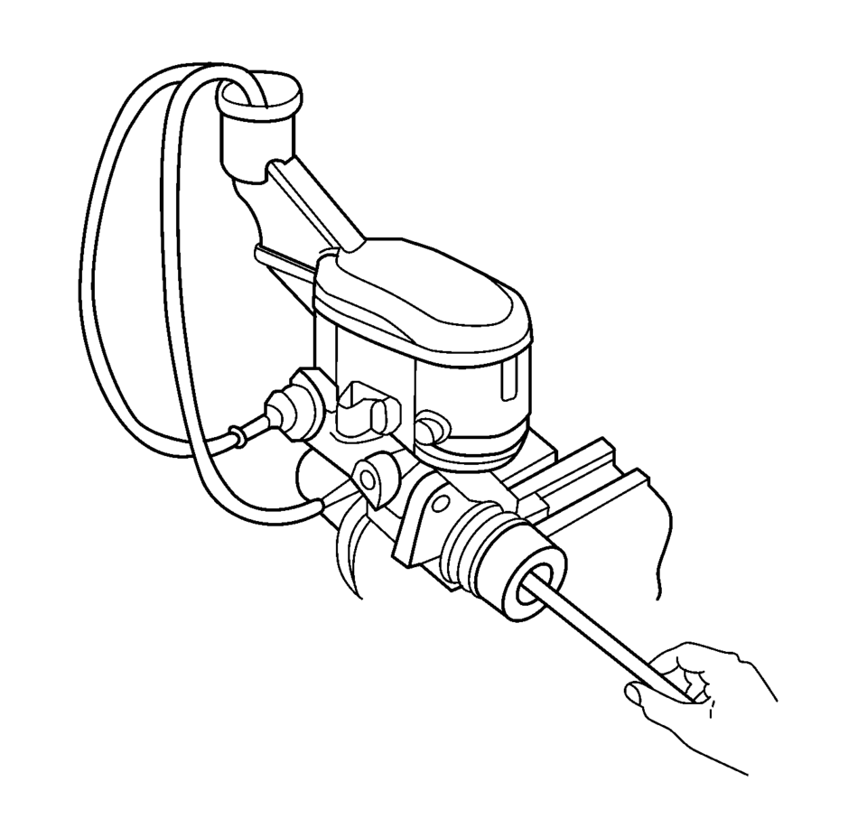
- Using a smooth, round-ended tool, depress and release the primary piston
as far as it will travel, a depth of about 25 mm (1 in), several times. Observe
the flow of fluid coming from the ports.
As air is bled from the primary and secondary pistons, the effort required to depress the primary piston will increase and the amount of travel will decrease.
- Continue to depress and release the primary piston until fluid flows freely from the ports with no evidence of air bubbles.
- Remove the transparent hoses from the master cylinder reservoir.
- Install the master cylinder reservoir cap and diaphragm.
- Remove the fittings with the transparent hoses from the master cylinder ports. Wrap the master cylinder with a clean shop cloth to prevent brake fluid spills.
- Remove the master cylinder from the vice.
Warning:
Refer to Brake Fluid Irritant Warning.
Caution:
Refer to Brake Fluid Effects on Paint and Electrical Components Caution.
 Brake Warning System Description and Operation
Brake Warning Indicator
Brake Warning Block Diagram
B80Park
Brake
SwitchB20Brake
Fluid Level
SwitchK9Body
Control
ModuleP16Inst ...
 Master Cylinder Replacement
Removal Procedure
Warning: Refer to Brake Fluid Irritant Warning.
Caution: Refer to Brake Fluid Effects on Paint and Electrical
Components Caution.
Place the ignit ...
Other materials:
Selecting the Alert Timing
The Collision Alert control is on the steering wheel. Press COLLISION ALERT to
set the alert timing to far, medium, near or off. The first button press shows the
current control setting on the DIC. Additional button presses will change this setting.
The chosen setting will remain until it is ...
Engine Overheating
The vehicle has an indicator to warn of the engine overheating.
If the decision is made not to lift the hood when this warning appears, get service
help right away. See Roadside Assistance Program.
If the decision is made to lift the hood, make sure the vehicle is parked on
a level surface.
T ...
Control Valve Body Cleaning and Inspection (Gen 2)
Control Valve Body Cleaning and Inspection
Callout
Component Name
Warning: Valve springs can be tightly compressed. Use care
when removing retainers and plugs. Personal injury could result.
Caution: After cle ...

0.0066