Chevrolet Sonic Repair Manual: Neutral - Engine Running (Gen 1)
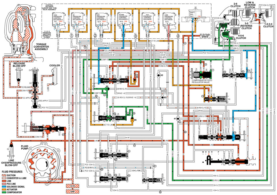
When the gear selector is moved to the Neutral (N) position, the hydraulic and electrical system operation is identical to Park (P) range. However, if Neutral is selected after the vehicle was operating in Reverse (R), the normally-high 35R pressure control solenoid 2 is commanded OFF and the following changes would occur in the hydraulic system.
- 3-5 Reverse Clutch Releases
-
Manual Valve
The manual valve is moved to the Neutral position and blocks line pressure from entering the reverse fluid circuit. Reverse fluid, from the 3-5-reverse clutch regulator valve and the clutch select valve, is opened to an exhaust passage at the manual valve.
35R Pressure Control Solenoid 2
The 35R PC solenoid 2 is commanded OFF allowing PCS 35 reverse clutch fluid from the 3-5-reverse clutch regulator valve to exhaust.
3-5-Reverse Clutch Regulator Valve
PCS 35 reverse clutch fluid exhausts, allowing 3-5-reverse clutch regulator valve spring force to move the 3-5-reverse clutch regulator valve to the released position. This allows 35 reverse clutch fluid pressure to exhaust into the compensator feed circuit in order to assist the 3-5-reverse clutch piston spring to quickly release the 3-5-reverse clutch.
3-5-Reverse Clutch
3-5-reverse clutch spring force, assisted by compensator feed pressure, moves the 3-5-reverse clutch piston to release the 3-5-reverse clutch plates and force 35 reverse clutch fluid to exhaust from the 3-5-reverse and 4-5-6 clutch housing assembly. The exhausting 35 reverse clutch fluid pressure is routed to the 3-5-reverse clutch regulator valve where it enters the 35 reverse clutch feed/compensator feed circuit.
Clutch Select Valve
When reverse fluid exhausts from the default override shuttle valve, shift solenoid fluid continues to hold the clutch select valve against clutch select valve spring force allowing 35 reverse clutch feed fluid to exhaust into the reverse circuit.
- Neutral?Engine Running
low mc reverse clutch solenoid solenoid n.h or; nh on nl 3-5 reverse clutch clutch 4-5-6 clutch tofioue converter assembly release cooler compensator feed regulator valve pcs mc pcs35 revcl unvfd tddapp -lwe fluid pressures suction converter lube line pcs line solenoid actuator compensatdr _1234 cl cl
 Manual Shift Shaft and Seal Replacement
Special Tools
DT-45201 Cooler Line Seal Remover
DT-49101 Seal Installer
For equivalent regional tools, refer to Special Tools.
Removal Procedure
Remove the battery tray. Refer ...
 Neutral - Engine Running (Gen 2)
When the gear selector is moved to the Neutral (N) position, the hydraulic and
electrical system operation is identical to Park (P) range. However, if Neutral
is selected after the vehicle was ope ...
Other materials:
Rear Window Wiper/ Washer
If equipped with the rear wiper/ washer, the controls are on the end of the windshield
wiper lever.
ON: Press the upper portion of the button for continuous rear window wipes.
OFF: The rear wiper turns off when the button is returned to the middle position.
INT (Intermittent Rear Wipes): Pres ...
Warning Lights, Gauges, and Indicators
Warning lights and gauges can signal that something is wrong before it becomes
serious enough to cause an expensive repair or replacement. Paying attention to
the warning lights and gauges could prevent injury.
Warning lights come on when there could be a problem with a vehicle function.
Some ...
Use of Room Temperature Vulcanizing (RTV) and Anaerobic Sealant
Pipe Joint Compound
Note: Three types of sealer are commonly used in engines. These
are RTV sealer, anaerobic gasket eliminator sealer, and pipe joint compound.
The correct sealer and amount must be used in the proper location to prevent
oil leaks. DO NOT interchange the 3&# ...

0.0065