Chevrolet Sonic Repair Manual: Park - Engine Running (Gen 1)
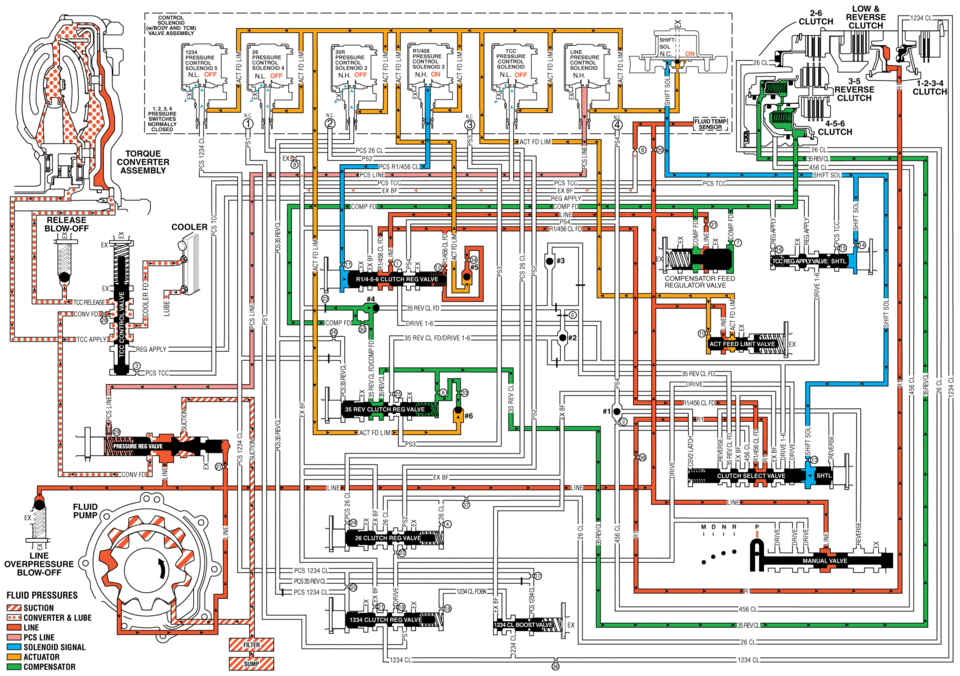
When the gear selector lever is in the Park (P) position, fluid is drawn into the pump through the transmission fluid filter assembly. Line pressure is then directed to the following valves:
- Fluid Pressure Directed in Preparation for a Shift
-
Manual Valve
Mechanically controlled by the gear selector lever, the manual valve is in the Park (P) position and prevents line pressure from the pressure regulator valve from entering the reverse and drive fluid circuits.
Actuator Feed Limit Valve
Line pressure is regulated through the valve into the actuator feed limit circuit. Actuator feed limit fluid passes through orifice #10 to a differential area to move the valve against actuator feed limit valve spring pressure. Actuator feed limit fluid is routed to the pressure control solenoids, the shift solenoid, and to the #5 and #6 ball check valves.
Compensator Feed Regulator Valve
Line pressure is regulated through the valve into the compensator feed fluid circuit. Compensator feed fluid pressure is routed through orifice #30 to the 3-5-reverse clutch regulator valve, and also fills the 3-5-reverse clutch and 4-5-6 clutch piston dam areas.
3-5-Reverse Clutch Regulator Valve
35 reverse clutch feed/compensator feed fluid is routed through the valve into the 35 reverse clutch fluid circuit. 35 reverse clutch fluid passes through orifice #6 to assist spring pressure in keeping the valve open. 35 reverse clutch fluid is routed to the 3-5-reverse clutch, and through orifice #33 to the #6 ball check valve.
3-5-Reverse Clutch Assembly
35 reverse clutch fluid fills the 3-5-reverse clutch piston apply cavity in preparation for a shift to Reverse range. However, in Park range, 35 reverse clutch pressure is limited to compensator feed pressure of 9 PSI and is not strong enough to apply the clutch.
TCC Regulated Apply Valve
Shift solenoid fluid is routed to the TCC regulated apply valve and moves the valve against TCC regulated apply valve spring force.
- Low and Reverse Clutch Applies
-
R1/456 Pressure Control (PC) Solenoid 3
The R1/456 PC solenoid is energized (ON) allowing actuator feed limit fluid to enter the PCS R1/456 clutch fluid circuit. PCS R1/456 clutch fluid is then routed through orifice #11 to the R1/4-5-6 clutch regulator valve.
R1/4-5-6 Clutch Regulator Valve
PCS R1/456 clutch fluid at the R1/4-5-6 clutch regulator valve, opposes R1/4-5-6 clutch regulator spring force and R1/456 clutch feed fluid pressure to regulate line pressure into the R1/456 clutch feed circuit. R1/456 clutch feed fluid is routed to the clutch select valve and through orifice #34 to the #5 ball check valve.
Shift Solenoid
The shift solenoid is energized (ON) allowing actuator feed limit fluid to enter the shift solenoid circuit. Shift solenoid fluid is routed to the clutch select valve through orifice #13, and to the TCC regulated apply valve through orifice #14.
Clutch Select Valve
Shift solenoid fluid is routed to the clutch select valve and moves the valve against clutch select valve spring force. This allows R1/456 clutch feed fluid to pass through the valve and enter the R1 circuit. R1 fluid is then routed through orifice #38 to the low and reverse clutch assembly in preparation for a shift into low or reverse gear.
Low and Reverse Clutch
R1/456 fluid enters the transmission case assembly and moves the low and reverse clutch piston against spring force to apply the low and reverse clutch plates. In Park range, the low and reverse has no effect. However, when Reverse or a forward range is selected, only one apply device has to be energized, which helps create a smooth starting motion.
#5 Ball Check Valve
R1/456 clutch feed fluid unseats the #5 ball check valve, allowing excess pressure to pass into the actuator feed limit circuit. This helps to control clutch apply fluid pressure and clutch apply feel.
- Park?Engine Running
closen tohoue converter assemblv release c0 unv fd tdd app blow-off fluid pressures suction converter lube line pcs line solenoid actuator compensatdr low reverse >< clutch clutch nl off solencm nl off smzuom nh on off olefi 1-2-3-4 clutch reverse clutch 4-5-6 clutch pcs tdc line compensator feed regulator valve 25 cl fd 234 cl passive. sol manual valve cl cl
 Output Speed Sensor Replacement
Output Speed Sensor Replacement
Callout
Component Name
Preliminary Procedure
Remove the control valve body. Refer to Control
...
 Park - Engine Running (Gen 2)
When the gear selector lever is in the Park (P) position, fluid is drawn into
the pump through the transmission fluid filter assembly. Line pressure is then directed
to the following valves:
...
Other materials:
Door Lock and Ignition Lock Folding Key Blade Removal and Installation
Special Tools
BO-51098 Flip Key Blade Fixture
For equivalent region tools, refer to Special Tools.
Caution: Failure to properly support the Remote Keyless Entry
(RKE) transmitter assembly while replacing the key blade may cause internal
damage to the transmitter assembly. ...
Special Tools
Illustration
Tool Number/Description
EL 38758
EL 50074
J 38758
Parasitic Draw Test Switch
EL 50313
EL 42000
EL 50076
J 42000
...
Oil Pan Replacement
Special Tools
EN-49980 Guidance Pins
For equivalent regional tools, refer to Special Tools.
Removal Procedure
Remove the right front wheelhouse liner extension. Refer to Front Wheelhouse
Liner Inner Front Extension Replacement.
Remove the oil filter and drain the engine oi ...

0.0083