Chevrolet Sonic Repair Manual: Park - Engine Running (Gen 2)
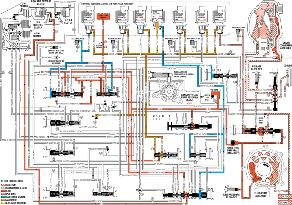
When the gear selector lever is in the Park (P) position, fluid is drawn into the pump through the transmission fluid filter assembly. Line pressure is then directed to the following valves:
- Fluid Pressure Directed in Preparation for a Shift
-
Manual Valve
Mechanically controlled by the gear selector lever, the manual valve is in the Park (P) position and prevents line pressure from the pressure regulator valve from entering the reverse and drive fluid circuits.
Actuator Feed Limit Valve
Line pressure is regulated through the valve into the actuator feed limit circuit. Actuator feed limit fluid passes through orifice #10 to a differential area to move the valve against actuator feed limit valve spring pressure. Actuator feed limit fluid is routed to the pressure control solenoids, the shift solenoid, and to the #4 ball check valve.
TCC Regulated Apply Valve
Shift solenoid fluid is routed to the TCC regulated apply valve and moves the valve against TCC regulated apply valve spring force.
Default Override Valve
Shift solenoid fluid is routed to the default override valve and moves the valve against default override valve spring force.
- Low and Reverse Clutch Applies
-
R1/456 Pressure Control (PC) Solenoid
The R1/456 PC solenoid is energized (ON) allowing actuator feed limit fluid to enter the PCS R1/456 clutch fluid circuit. PCS R1/456 clutch fluid is then routed through orifice #11 to the R1/4-5-6 clutch regulator valve, and through orifice #34 to the R1/4-5-6 clutch boost valve.
R1/4-5-6 Clutch Regulator Valve
PCS R1/456 clutch fluid at the R1/4-5-6 clutch regulator valve, opposes R1/4-5-6 clutch regulator spring force and orificed R1/456 clutch feedback fluid pressure to regulate line pressure into the R1/456 clutch feed circuit. R1/456 clutch feed fluid is routed to the R1/4-5-6 clutch boost valve and to the clutch select valve.
R1/4-5-6 Clutch Boost Valve
PCS R1/456 clutch fluid pressure acts on a differential area, moving the R1/4-5-6 clutch boost valve against R1/4-5-6 clutch boost valve spring force, to regulate R1/456 clutch feed fluid into the R1/456 clutch feedback circuit. As PCS R1/456 clutch fluid pressure is increased to a given value, the R1/4-5-6 clutch boost valve opens the R1/456 clutch feedback circuit to exhaust backfill. This results in the R1/4-5-6 clutch regulator valve moving to the full feed position, sending full R1/456 clutch feed pressure (full line pressure) to the low and reverse clutch.
Shift Solenoid
The shift solenoid is energized (ON) allowing actuator feed limit fluid to enter the shift solenoid circuit. Shift solenoid fluid is routed to the clutch select valve through orifice #13, to the TCC regulated apply valve through orifice #14, and through orifice #44 to the default override valve.
Clutch Select Valve
Shift solenoid fluid is routed to the clutch select valve and moves the valve against clutch select valve spring force. This allows R1/456 clutch feed fluid to pass through the valve and enter the R1 circuit. R1 fluid is then routed through orifice #42 to the low and reverse clutch assembly in preparation for a shift into low or reverse gear.
Low and Reverse Clutch
R1/456 fluid enters the transmission case assembly and moves the low and reverse clutch piston against spring force to apply the low and reverse clutch plates. In Park range, the low and reverse clutch has no effect. However, when Reverse or a forward range is selected, only one apply device has to be energized, which helps create a smooth starting motion.
Accumulator
PCS R1/456 clutch fluid is also routed to an accumulator valve. The accumulator valve is used to dampen any pressure irregularities occurring in the PCS R1/456 clutch fluid circuit. This helps to control clutch apply fluid pressure and clutch apply feel.
- Park ?EEngine Running ?E#8201;Gen 2/Hybrid
ldw and reverse clutcu_ solennid mus pres pre press pressure n.l-1. un off off off ex ancumumnn aceumhlatgr clutch tdrdue converter assembly exhaust arr ball actfd um ex lu to pcs cl clutch ex backhll cddleh blow-off ex badkhll u3 valve el line auxiliary fluid open pumpassembly (bas+) clutch feedback off ex ii suctiuu lwe lwe ex rev cl 35 reverse clutch actuator feed limtt sun up _/\ _35 rev clutch pcs reverse clutch default zex clutch: clutch ex fluid thru ehedkball pcszg clutch ex ex backhll pcs clutch clutch ngv clutch fd: fluid pressures sucnou lube latch line pressure solenoid signal clutch clutch :i
 Park - Engine Running (Gen 1)
When the gear selector lever is in the Park (P) position, fluid is drawn into
the pump through the transmission fluid filter assembly. Line pressure is then directed
to the following valves:
...
 Replacing Engine Gaskets
Gasket Reuse and Applying Sealants
Do not reuse any gasket unless specified.
Gaskets that can be reused will be identified in the service procedure.
Do not apply sealant to any ...
Other materials:
Brake System Warning Light
The vehicle brake system consists of two hydraulic circuits. If one circuit is
not working, the remaining circuit can still work to stop the vehicle. For normal
braking performance, both circuits need to be working
If the warning light comes on, there is a brake problem. Have the brake system
...
Water Outlet Replacement (LUV)
Removal Procedure
Drain the engine coolant system. Refer to Cooling System Draining and
Filling.
Remove the following:
Engine coolant air bleed hose (1)
Engine coolant temperature sensor (2) and connector clip (3)
Heated oxygen senso ...
Intake Camshaft Removal
Remove the camshaft bearing cap bolts in a spiral sequence as shown one
turn at a time until there is no spring tension pushing on the camshaft.
Note: Mind the markings on the camshaft bearing caps to ensure
they will be installed in the same position.
Remove the ...

0.0122