Chevrolet Sonic Repair Manual: Rear Wheel Speed Sensor Replacement
- Removal Procedure
-
Warning:
Refer to Brake Dust Warning.
- Raise and support the vehicle. Refer to Lifting and Jacking the Vehicle.
- Remove the tire and wheel assembly. Refer to Tire and Wheel Removal and Installation.
- Remove the rear wheel speed sensor harness connector cover nuts (1).
- Remove the rear wheel speed sensor harness connector cover (1).
- Clean the rear drum brake area around the wheel speed sensor of any accumulated dirt and debris.
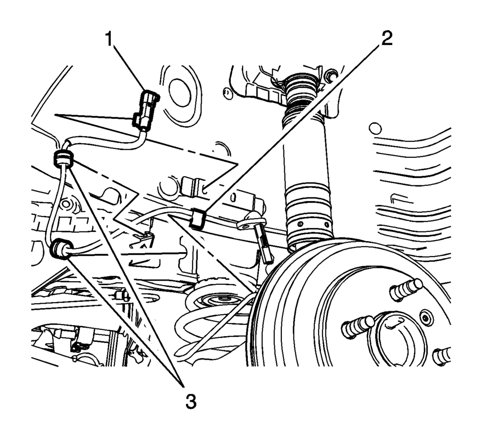
- Disconnect the wheel speed sensor electrical connector (1) and release the connector from the wheelhouse bracket.
- Release the wheel speed sensor harness retainer (2) from the wheel cylinder brake pipe.
- Release the wheel speed sensor harness grommets (3) from the bracket.
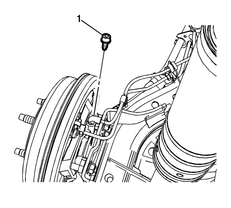
- Remove the wheel speed sensor bolt (1).
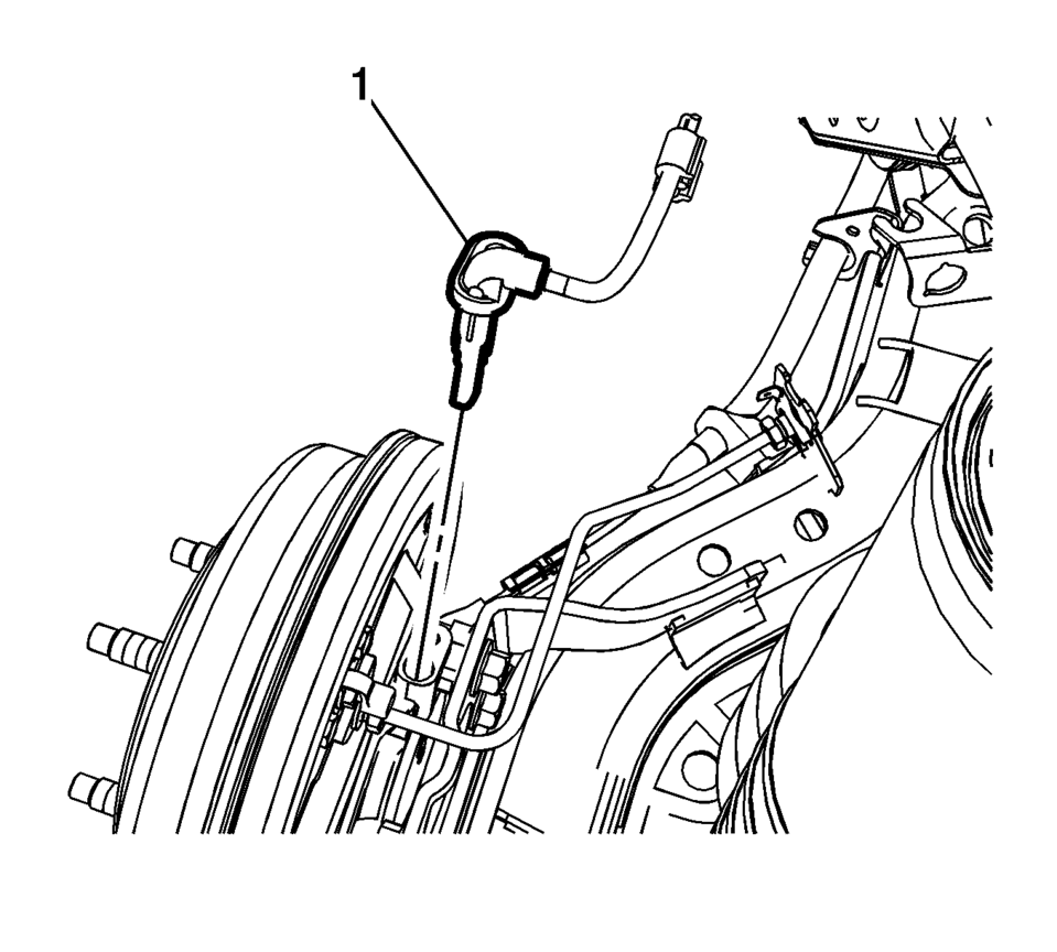
- Remove the wheel speed sensor (1) from the rear drum brake spacer by pulling the sensor straight upward using a slight twisting motion.


- Installation Procedure
-
- Install the wheel speed sensor (1) to the rear drum brake spacer.
- Install the wheel speed sensor bolt (1) and tighten to 8 Y (71 lb in)
.
- Connect the wheel speed sensor electrical connector (1) and install the connector to the wheelhouse bracket.
- Install the wheel speed sensor harness retainer (2) to the wheel cylinder brake pipe.
- Install the wheel speed sensor harness grommets (3) to the bracket.
- Install the rear wheel speed sensor harness connector cover (1).
- Install the rear wheel speed sensor harness connector cover nuts (1)
and tighten to 2 Y (18 lb in)
.
- Install the tire and wheel assembly. Refer to Tire and Wheel Removal and Installation.
- Perform the Diagnostic System Check - Vehicle.
Caution:
Refer to Fastener Caution.
Note:
If the wheel speed sensor grommets are equipped with a molded rib, position the grommets with the rib at the open end of the wheel speed sensor harness brackets. Do not twist the wheel speed sensor harness.
 Front Wheel Speed Sensor Replacement
Removal Procedure
Warning: Refer to Brake Dust Warning.
Raise and support the vehicle. Refer to Lifting and Jacking the Vehicle.
Remove the tire and wheel assembly. Refer ...
 Special Tools
Illustration
Tool Number/ Description
EL 35616-F
J 35616
Terminal Test Kit
...
Other materials:
Rear Window Defogger Description and Operation
Rear Window Defogger System Components
The rear window defogger system consist of the following components:
The HVAC control module
The body control module (BCM)
The rear defogger relay
The rear window grid
Driver outside rearview mirror
Passenger outside rearview mirro ...
Rear Seat Cushion Cover and Pad Replacement
Rear Seat Cushion Cover and Pad Replacement
Callout
Component Name
Preliminary Procedure
Remove the rear seat cushion. Refer to Rear Seat Cushion Removal and
Installation
1
Rear Seat Cushion Cov ...
Timing Belt Center Front Cover Replacement
Timing Belt Center Front Cover Replacement
Callout
Component Name
Preliminary Procedure
Remove the timing belt upper front cover. Refer to Timing Belt Upper
Front Cover Replacement.
Remove the engine mount bracket. Refer ...

0.0064