Chevrolet Sonic Repair Manual: Transmission Case Disassemble (Gen 2)
Special Tools
- 3-9506289 Universal Adapter
- J-810700 Mainshaft Bearing Remover
- J-810704 Center Bar Puller
- M-680770 Universal Sliding Mallet
- R-0007758 Holding Fixture
- R-0007770 Holding Fixture Adapter Plates
- T-0307000 Extractor and Driver Fixture
- T-9807671 Slide Hammer
For equivalent regional tools, refer to Special Tools.
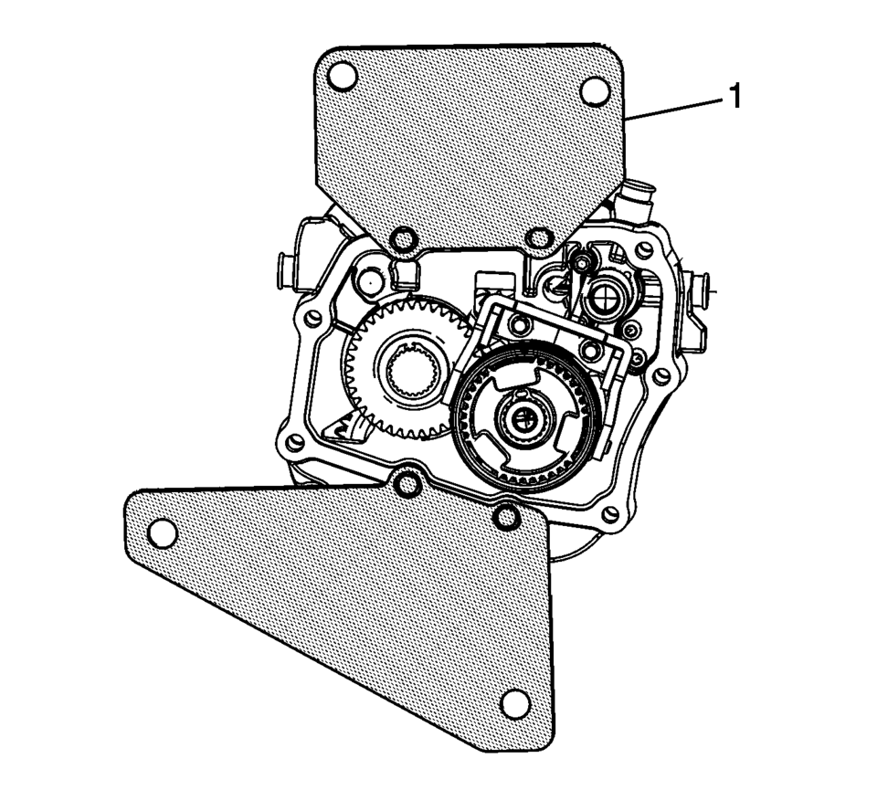
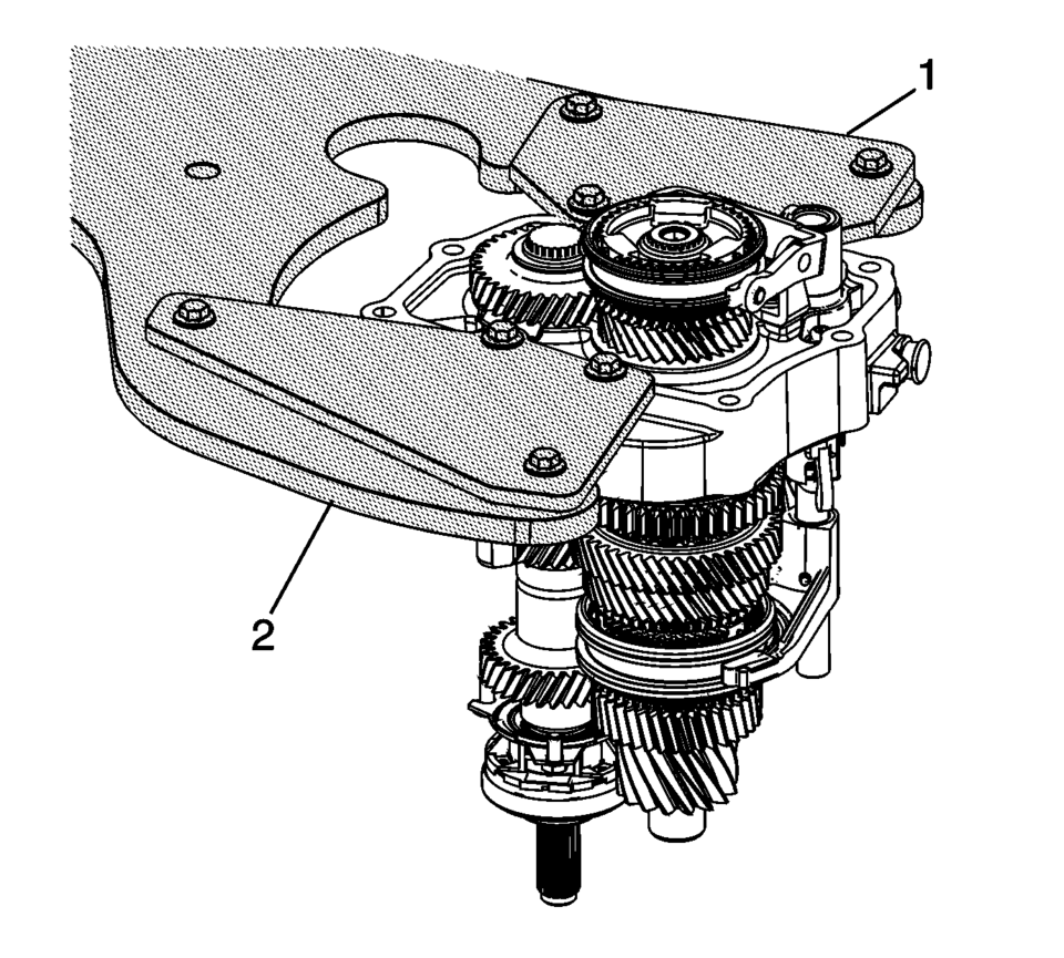
- Install both plates of the R-0007770 holding fixture adapter platesto the transmission case assembly (1).
- Install the transmission case, with the R-0007770 holding fixture adapter plates (1) to the R-0007758 holding fixture (2) and 3-9506289 universal adapter.
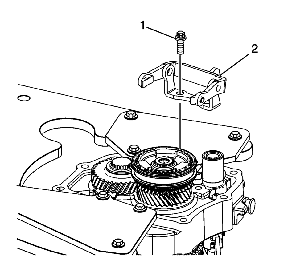
- Remove the 5th shift fork bracket retaining bolts (1).
- Remove the 5th shift fork bracket assembly (2).
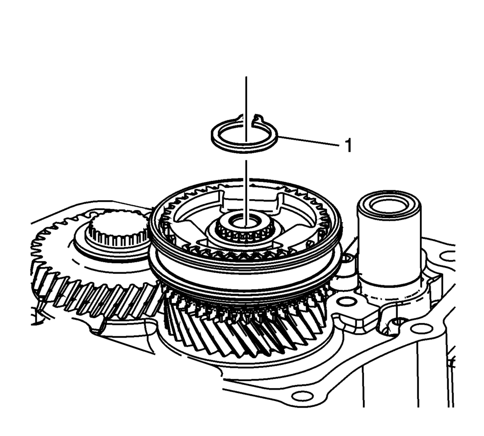
- Remove the 5th gear synchronizing hub retaining ring (1).
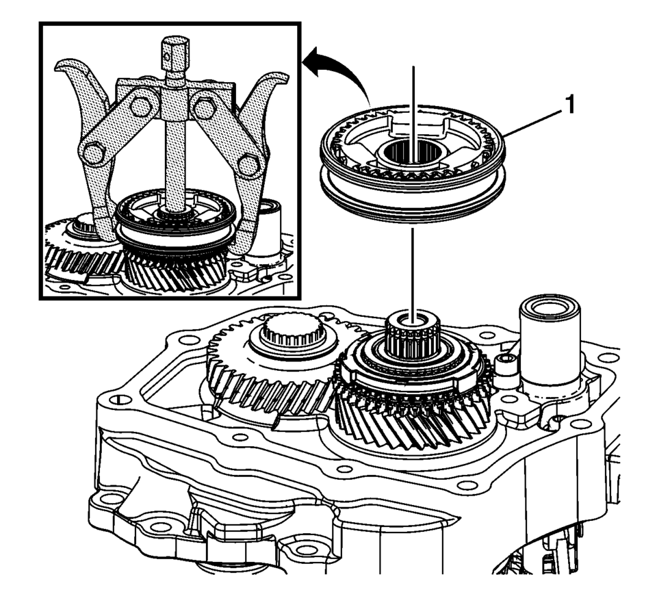
- Using the J-810704 puller, remove the 5th gear synchronizer assembly (1).
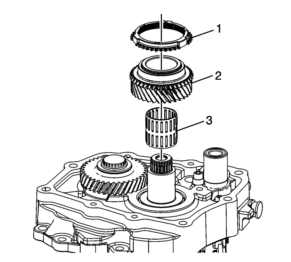
- Remove the 5th gear blocking ring (1).
- Remove the 5th gear assembly, driven (2).
- Remove the 5th gear bearing assembly (3).
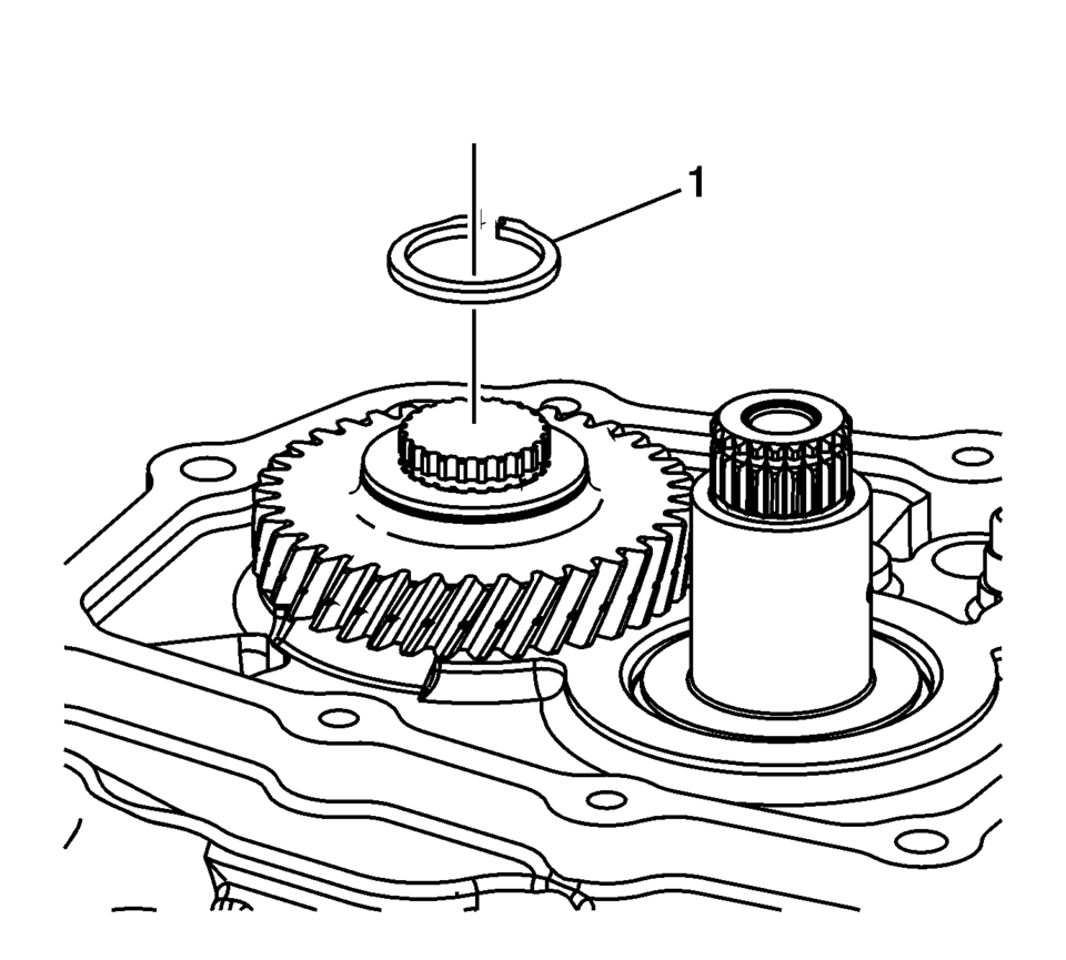
- Remove the 5th gear retaining ring (1).
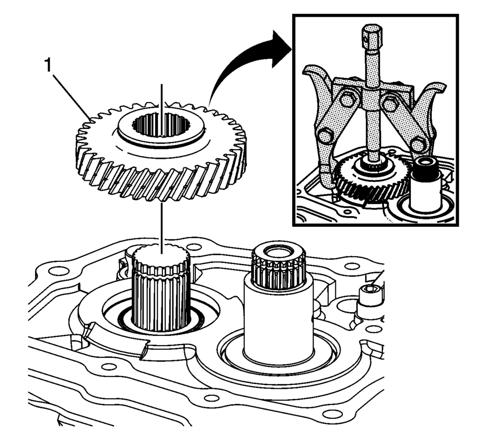
- Using the J-810704 puller, remove the 5th gear, driving (1).
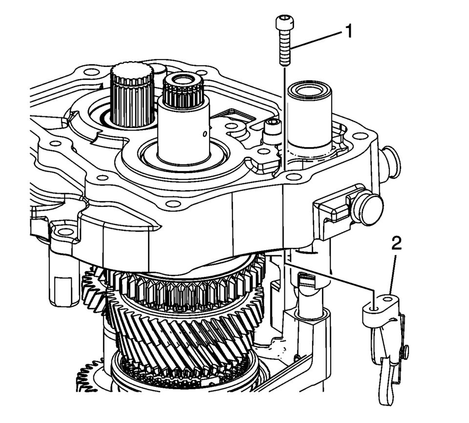
- Remove the parking pawl retaining bolts (1).
- Remove the parking pawl (2).
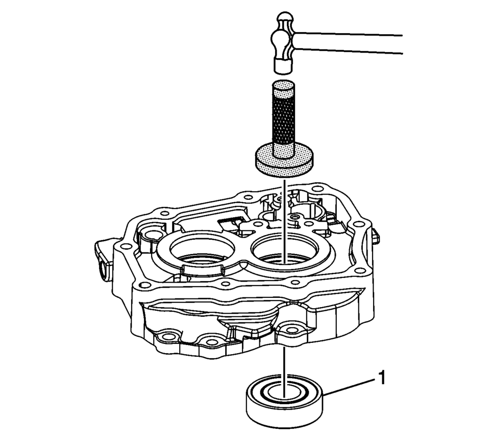
- Using the M-680770 sliding malletadapter (2) and the T-9807671 slide hammer (1), remove the 4 shift shaft detent sleeves (3?) from the transmission case.
- The bolts are micro-encapsulated and may require that the transmission case be heated to 80?C (176?F) with a heat gun.
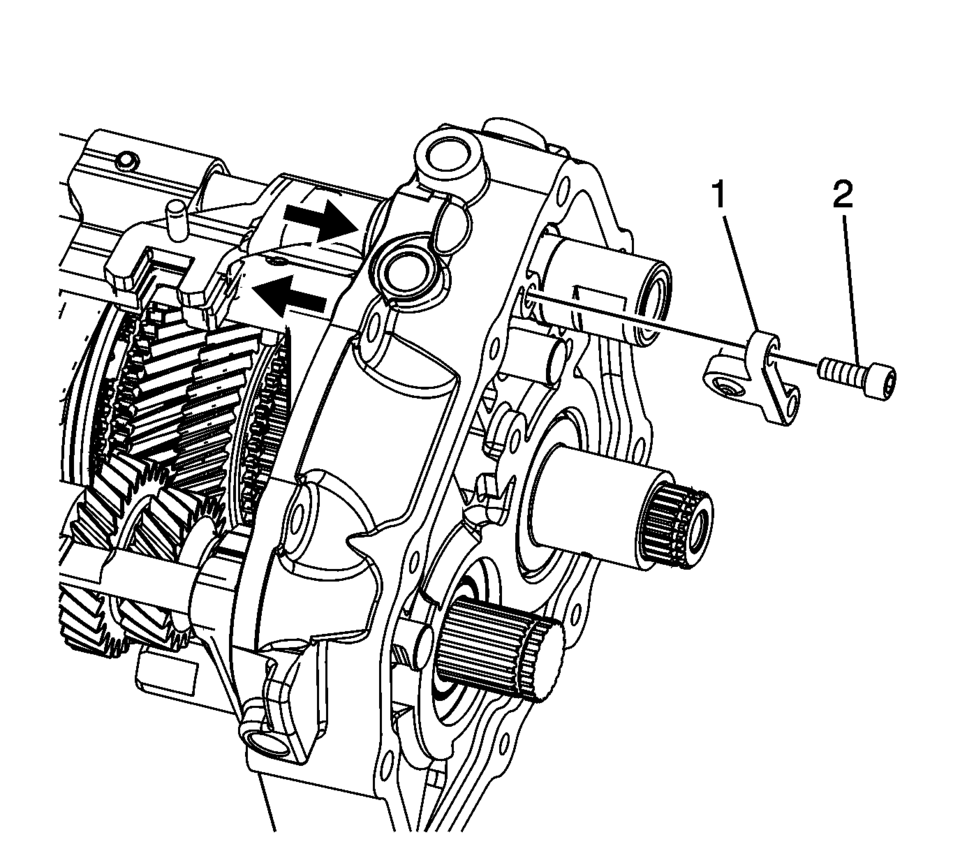
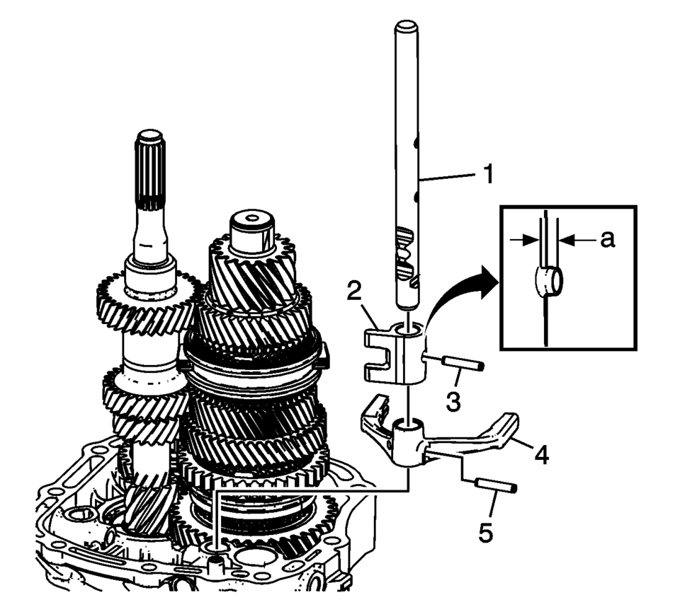
- Engage the shift shafts into 2nd gear, 5th gear, and 3rd gear as indicated with arrows to remove the interlock pin connector.
- Remove the shift shaft interlock pin connector bolts (2).
- Remove the shift shaft interlock pin connector (1).
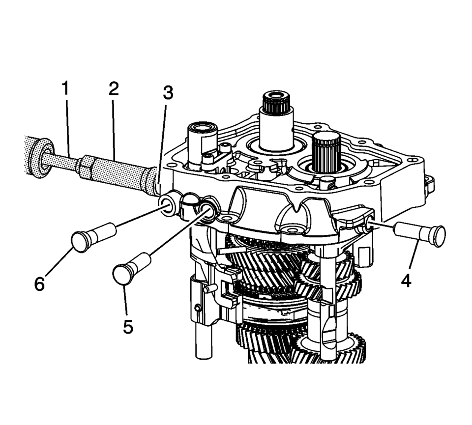
- Remove the reverse shift fork pin (4).
- Remove the reverse shift shaft (3).
- Remove the reverse shift fork (5).
- Remove the reverse fork block pin (2).
- Remove the reverse fork block (1).
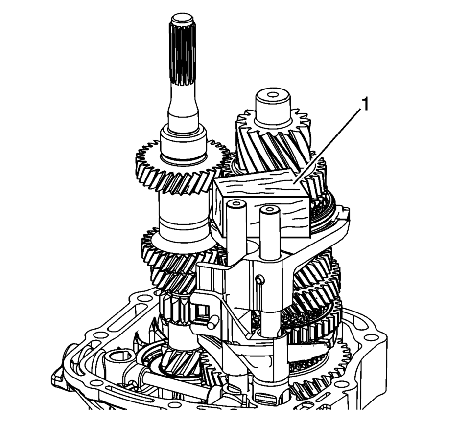
- Use a block of wood (1) to relieve the pressure on the gearshift rod guides.
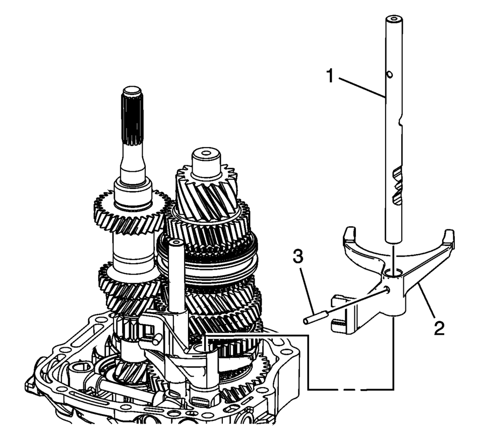
- Remove the 3rd and 4th shift fork pin (3).
- Remove the 3rd and 4th shift shaft (1).
- Remove the 3rd and 4th shift fork (2).
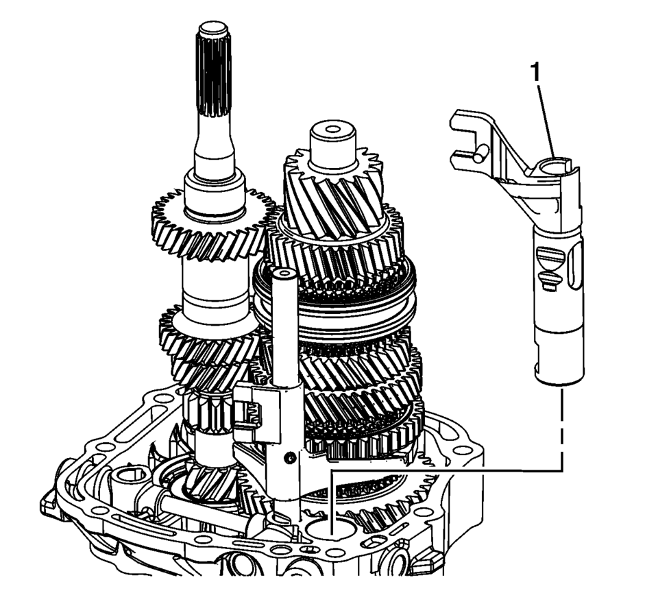
- Remove the 5th shift blocking guide (1) from the transmission case.
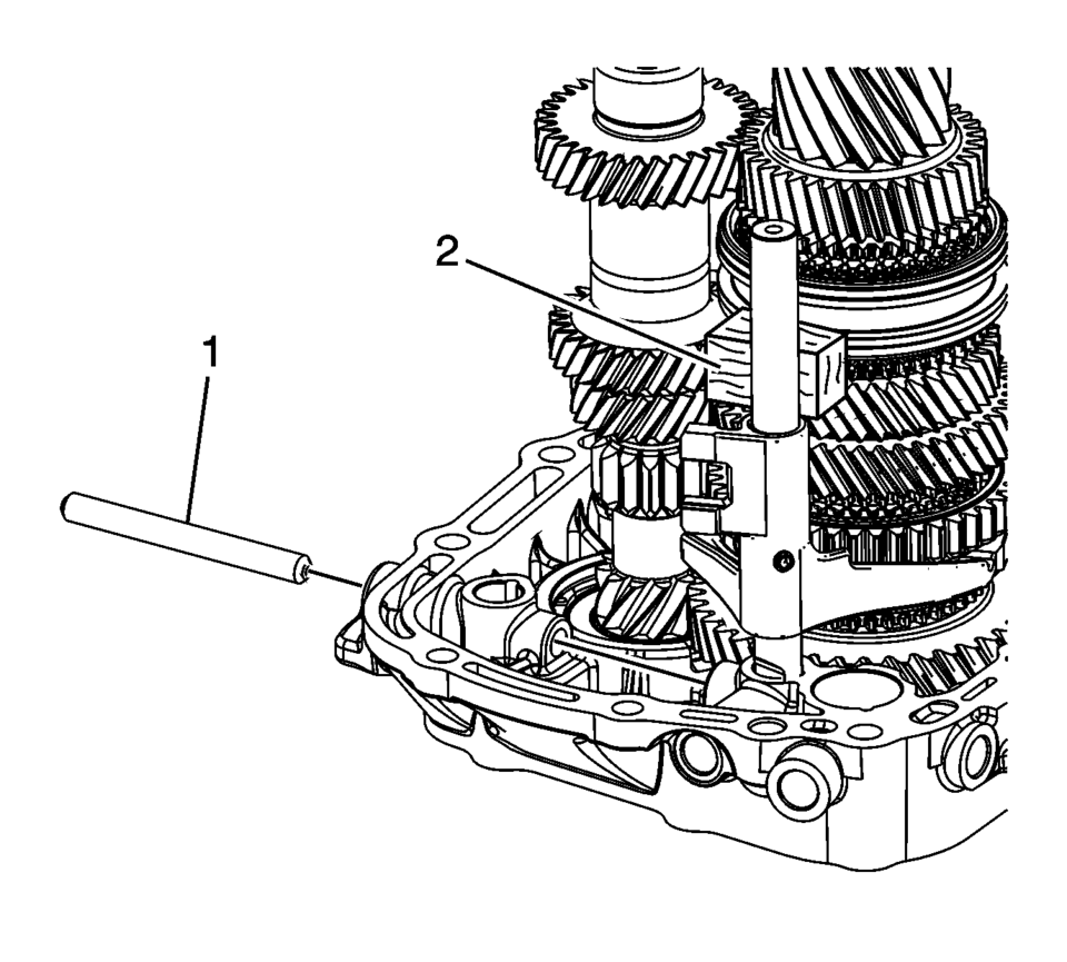
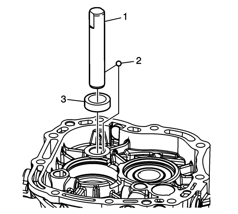
- Remove the gearshift rod (1) from the transmission case.
- Insert a block of wood (2) to relieve pressure on the gearshift rod guides.
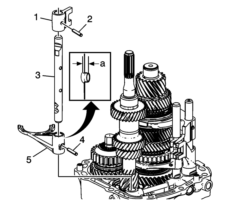
- Remove the 1st and 2nd shift fork pin (5).
- Remove the 1st and 2nd shift shaft (1).
- Remove the 1st and 2nd shift fork (4).
- Remove the 1st and 2nd shaft block pin (3).
- Remove the 1st and 2nd shaft block (2).
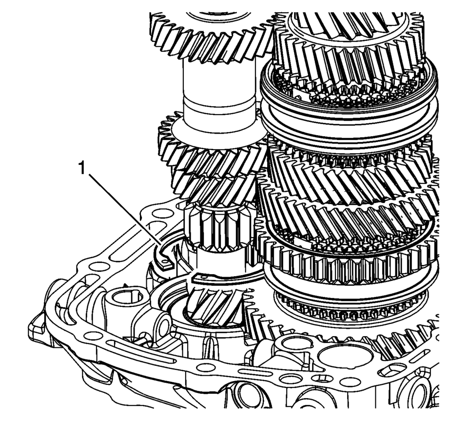
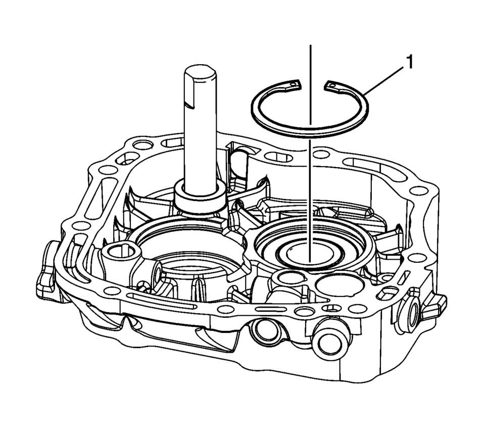
- Remove the input shaft bearing retaining ring (1) from the bore, and leave it on the shaft.
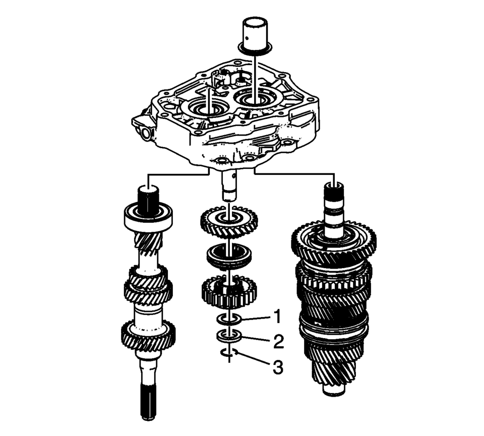
- Remove the reverse gear shaft snap ring (3) if equipped, reverse spur gear washer (2), and reverse spur gear bearing (1).
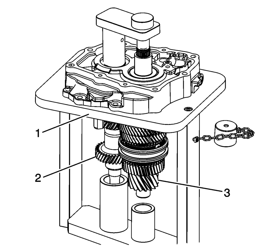
- Remove the transmission case from R-0007770 adapter plates and install onto the T-0307000 fixture.
- Support the mainshaft (3), input shaft (2) and reverse idler gear (1) while pressing the shafts from the case.
- Remove the following components from the T-0307000 fixture.
Note:
The parking pawl bolts are micro-encapsulated and may require that the transmission case be heated to 80?C (176?F) with a heat gun.
Note:
Note:
The reverse gear shaft snap ring (3) MUST be installed even if not originally equipped to prevent shifting issues caused by incorrect assembly or parts not in position.
Note:
Be prepared to support the reverse idler gear, input shaft and mainshaft as they are pressed from the case.
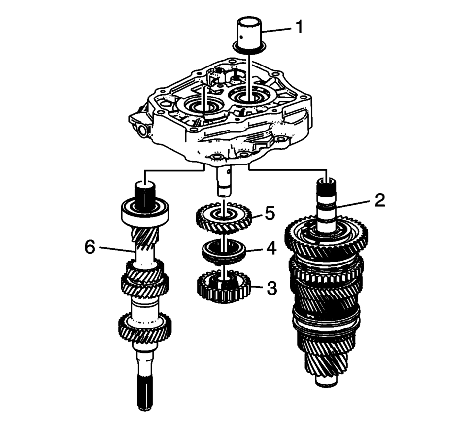
- Main shaft (2)
- Reverse spur gear (3)
- Reverse synchro assembly (4)
- Reverse helical gear (5)
- Input Shaft (6)
 Transmission Case Disassemble (Gen 1)
Special Tools
3-9506289 Universal Adapter
J-810700 Mainshaft Bearing Remover
J-810704 Center Bar Puller
M-680770 Universal Sliding Mallet
R-0007758 Holding Fixture
R-0007770 Holding F ...
 Transmission Control Lever Boot Replacement
Transmission Control Lever Boot Replacement
Callout
Component Name
Preliminary Procedure
Remove the front floor console. Refer ...
Other materials:
Instrument Panel Lower Trim Pad Cover Replacement (Without AAL)
Instrument Panel Lower Trim Pad Cover Replacement
Callout
Component Name
1
Instrument Panel Lower Trim Pad Fastener (Qty:?€‰2)
Caution: Refer to Fastener Caution.
2
Instrumen ...
Front Wheel Drive Shaft Inner Joint and Boot Replacement
Special Tools
DT-35910 Drive Axle Boot Clamp Pliers
For equivalent regional tools, refer to Special Tools.
Disassemble Procedure
Note: There are types of inner joints available. If the inner
joint is connected with the CV style joint, the inner joint is not serviced
separa ...
Transmission Fluid Level and Condition Check
Removal Procedure
Raise and support the vehicle. Refer to
Lifting and Jacking the Vehicle
Remove the front suspension skid plate, if equipped.
Refer to Drivetrain and Front Suspension Frame Skid
Plate Replacement
Place a basin underneath the vehicle.
Clean away all ...

0.0113