Chevrolet Sonic Repair Manual: Transmission Replacement (With 1.2L or 1.4L Engine)
- Removal Procedure
-
- Remove the battery tray. Refer to Battery Tray Replacement.
- Without draining the coolant or removing the hoses, remove and position aside the radiator surge tank. Refer to Radiator Surge Tank Replacement.
- Remove the transmission range selector lever cable. Refer to Range Selector Lever Cable Replacement.
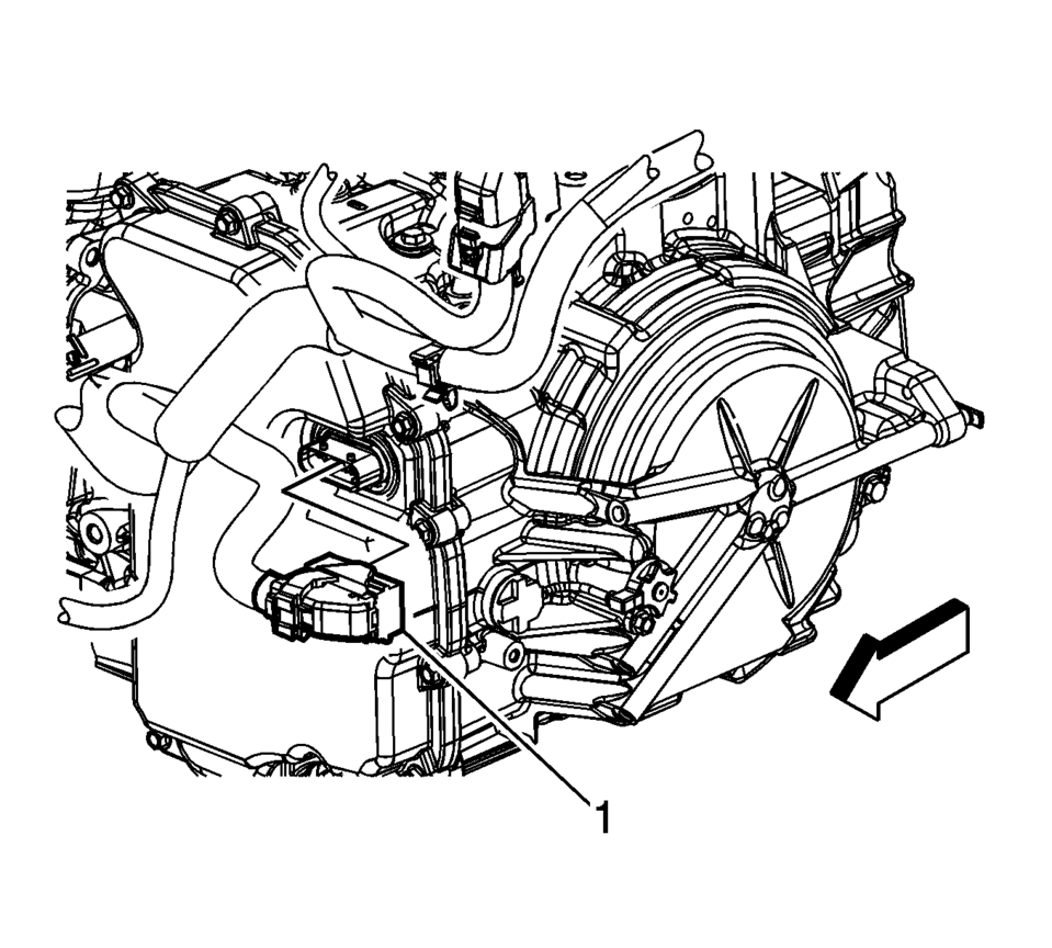
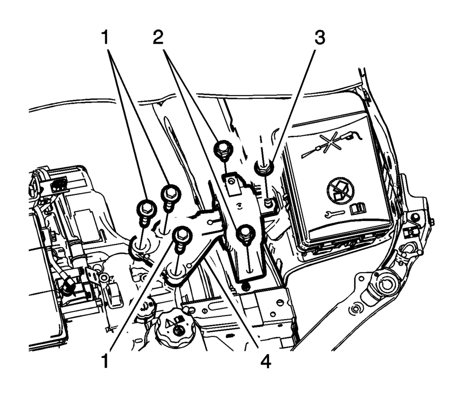
- Disconnect the control valve body transmission control module electrical connector (1) then unclip the connector from the transmission.
- Remove the transmission fluid cooler inlet hose from the transmission. Refer to Fluid Cooler Inlet Hose Replacement.
- Remove the transmission fluid cooler outlet hose from the transmission. Refer to Fluid Cooler Outlet Hose Replacement.
- Plug and/or cap the pipes and transmission to prevent contamination.
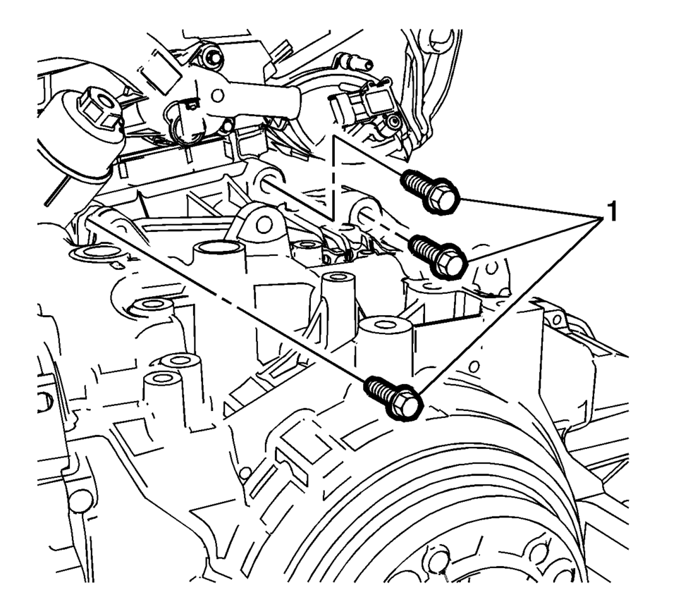
- Remove the upper transmission to engine bolts (1).
- Install the support fixture. Refer to Engine Support Fixture.
- Drain the transmission fluid. Refer to Transmission Fluid Drain and Fill.
- Remove the front exhaust pipe. Refer to Exhaust Front Pipe Replacement.
- Remove the front wheel drive shafts from the transmission. Refer to Front Wheel Drive Shaft Replacement.
- Remove the starter motor. Refer to Starter Replacement.
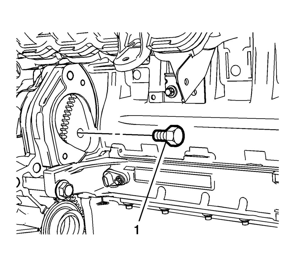
- Mark the relationship of the flywheel to the torque converter for reassembly.
- Remove the torque converter to flywheel bolts (1).
- Remove the drivetrain and front suspension frame. Refer to Drivetrain and Front Suspension Frame Replacement.
- Remove the rear transmission mount bracket from the transmission. Refer to Transmission Mount Bracket Replacement - Rear.
- Remove the left transmission mount (4). Refer to Transmission Mount Replacement - Left Side.
- Use a transmission jack in order to support the transmission.
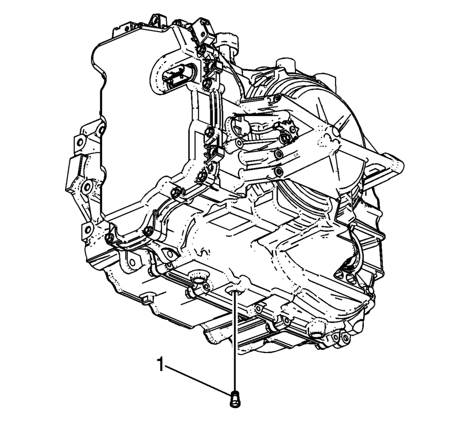
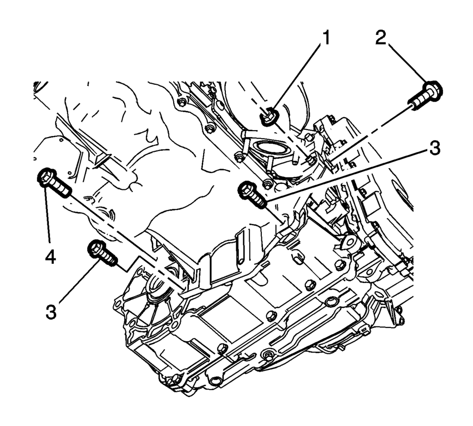
- Remove the lower transmission nut (1) and the lower transmission bolts (2?E).
- Separate the transmission from the engine.
- Lower the transmission with the transmission jack far enough to remove the transmission.
- Flush and flow test the transmission oil cooler and lines. Refer to Transmission Fluid Cooler Flushing and Flow Test.
Note:
Ensure the torque converter remains securely in place on the transmission input shaft while separating and removing the transmission.
- Installation Procedure
-
- Raise the transmission with the transmission jack and position the transmission to the engine.
- Install the lower transmission bolts (2, 4) and tighten to 60 Y (44 lb ft)
.
- Install the lower transmission bolts (3) and the lower transmission
nut (1) and tighten to 40 Y (30 lb ft)
.
- Remove the transmission jack.
- Install the left transmission mount (4). Refer to Transmission Mount Replacement - Left Side.
- Install the rear transmission mount bracket to the transmission. Refer to Transmission Mount Bracket Replacement - Rear.
- Install the drivetrain and front suspension frame. Refer to Drivetrain and Front Suspension Frame Replacement.
- Install the torque converter to flywheel bolts (1) and tighten to
60 Y (44 lb ft)
.
- Install the starter motor. Refer to Starter Replacement.
- Install the front wheel drive shafts to the transmission. Refer to Front Wheel Drive Shaft Replacement.
- Install the front exhaust pipe. Refer to Exhaust Front Pipe Replacement.
- Remove the support fixture. Refer to Engine Support Fixture.
- Install the upper transmission to engine bolts (1) and tighten to
60 Y (44 lb ft)
.
- Connect the control valve body transmission control module electrical connector (1) then clip the connector to the transmission.
- Install the transmission fluid cooler outlet hose to the transmission. Refer to Fluid Cooler Outlet Hose Replacement.
- Install the transmission fluid cooler inlet hose to the transmission. Refer to Fluid Cooler Inlet Hose Replacement.
- Install the transmission range selector lever cable. Refer to Range Selector Lever Cable Replacement.
- Adjust the automatic transmission range selector lever cable. Refer to Range Selector Lever Cable Adjustment.
- Install the radiator surge tank. Refer to Radiator Surge Tank Replacement.
- Install the battery tray. Refer to Battery Tray Replacement.
- Fill the transmission with fluid. Refer to Transmission Fluid Drain and Fill.
- If a NEW transmission control module (TCM) has been installed into the vehicle, the NEW module needs to be reprogrammed. Refer to Service Programming System (SPS).
- Transmission internal service/overhaul
- Valve body repair or replacement
- Control solenoid valve assembly replacement
- TCM software/calibration update
- Any service in response to a shift quality concern
- Perform the transmission adaptive values learn. Refer to Transmission Adaptive Values Learn.
- Road test the vehicle.
Caution:
Refer to Fastener Caution.
Note:
If reusing the torque converter bolts, clean the threads and apply threadlocker to the threads prior to installation.
Note:
The transmission adaptive values learn procedure must be performed when one of the following repairs have been made to the vehicle. Failure to perform the procedure after one of the following repairs may result in poor transmission performance, as well as transmission DTCs being set:
 Tools and Equipment
Special tools are listed and illustrated throughout this section with a complete
listing at the end of the section. These tools, or their equivalents, are specially
designed to quickly and safely ...
 Transmission Replacement (With 1.6L or 1.8L Engine)
Removal Procedure
Remove the battery tray. Refer to Battery Tray Replacement.
Without draining the coolant or removing the hoses, remove and position
aside the radiator surge tank ...
Other materials:
Adhesive Installation of Liftgate Windows
Warning: Refer to Glass and Sheet Metal Handling Warning.
Use a urethane adhesive systems which meet GM Specification GM?€‰3651G.
Remove all mounds or loose pieces of urethane adhesive from the pinchweld
area.
If the original window is being reused, remove all but approxi ...
Floor Air Outlet Duct Replacement - Right Side (LHD)
//
Floor Air Outlet Duct Replacement - Right Side
Callout
Component Name
Preliminary Procedure
Remove the instrument panel insulator, if equipped.
1
Floor Air Outlet Duct Fastener
2
...
Water Pump Installation
Clean the sealing surfaces and the 3 coolant pump threads.
Install NEW gasket.
Caution: Refer to Fastener Caution.
Caution: Refer to Torque-to-Yield Fastener Caution.
Install the coolant pump (1).
Install 5 NEW bolts (2) and tighten to 8& ...

0.0112