Chevrolet Sonic Repair Manual: Camshaft Timing Chain Inspection
Special Tools
- EN-952 Fixing Pin
- EN-953-A Fixing Tool
- EN-49977-100 Transmitter Disc Fixation
For equivalent regional tools, refer to Special Tools.
- Remove the ignition coil. Refer to Ignition Coil Replacement.
- Remove the camshaft cover. Refer to Camshaft Cover Replacement.
- Remove the right front wheelhouse liner. Refer to Front Wheelhouse Liner Replacement
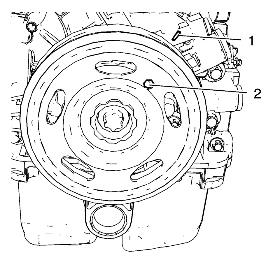
- Rotate the engine clockwise until the bore (2) in the crankshaft balancer aligns with the mark (1) on the engine front cover.
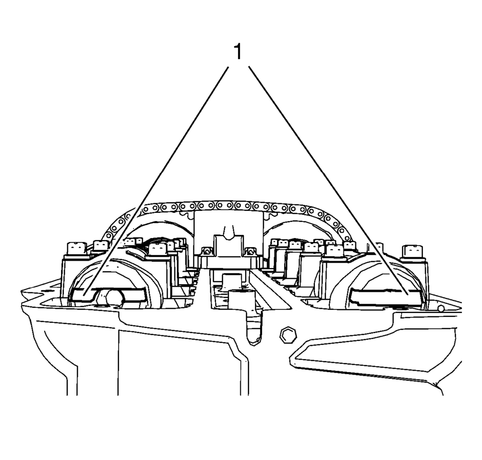
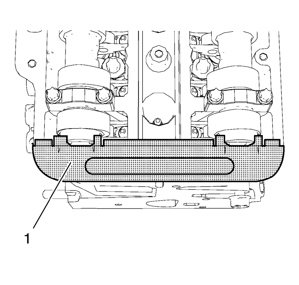
- Examine that the camshaft grooves (1) are visible as shown. If the camshaft grooves are not visible rotate the crankshaft 360┬░.
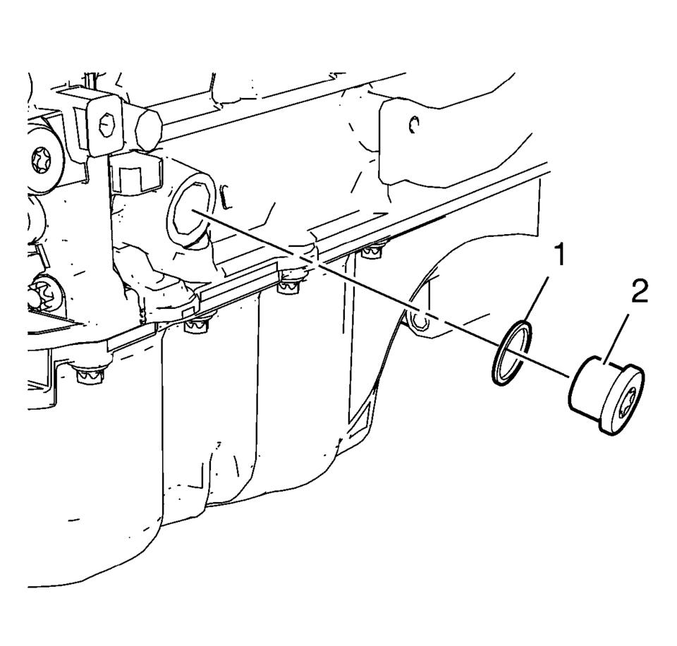
- Remove the crankshaft bearing cap tie plate hole plug (2) and the seal ring (1).
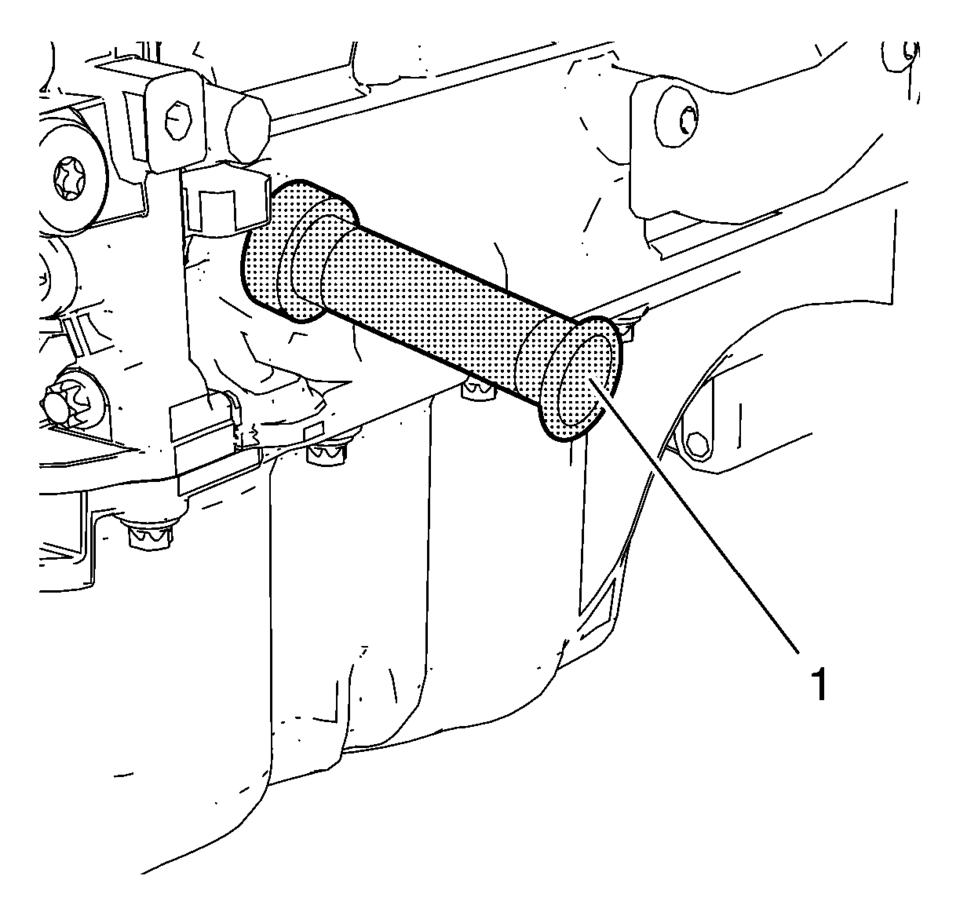
- Install EN-952 fixing pin (1) to hold the crankshaft in TDC position.
- Install EN-953-A fixing tool (1) to the camshafts.
- Install EN-49977-100 transmitter disc fixation (1) to inspect the correct position of the camshaft position exciter wheels.
- Tighten the bolts (2) of EN-49977-100 transmitter disc fixation .
- If EN-953-A fixing tool or EN-49977-100 transmitter disc fixation can not be installed, refer to Camshaft Timing Chain Adjustment.
- Remove EN-49977-100 transmitter disc fixation .
- Remove EN-953-A fixing tool .
- Remove EN-952 fixing pin .
- Install crankshaft bearing cap tie plate hole plug and seal ring and tighten
to 40 Y (30 lb ft)
.
- Install the right front wheelhouse liner. Refer to Front Wheelhouse Liner Replacement
- Install the camshaft cover. Refer to Camshaft Cover Installation.
- Install the ignition coil. Refer to Ignition Coil Installation.
Caution:
To ensure proper crankshaft top dead center (TDC) alignment, the retention pin should fit easily through the bore in the crankshaft tie plate and into the crankshaft. Binding of the retention pin could affect proper engine timing.
Note:
The fixing tool should be installed completely to both camshaft grooves without high effort.
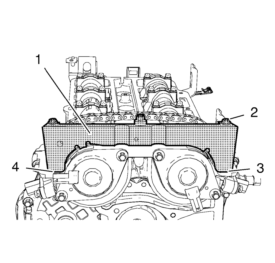
Note:
A wrong installation position is possible. Make sure that the fixation tool is installed without clearance to the cylinder head in areas (3) and (4).
Caution:
Refer to Fastener Caution.
 Camshaft Timing Chain Adjustment
Special Tools
EN-952 Fixing Pin
EN-953ŌĆōA Fixing Tool
EN-49977?E00 Fixation Sensor Discs
For equivalent regional tools, refer to Special Tools.
Remove the ignition coil. Refer to Ign ...
 Camshaft Timing Chain Installation
Special Tools
EN-952 Fixing Pin
EN-953-A Fixing Tool
EN-955-10 Fixing Pin from EN-955 Kit
For equivalent regional tools, refer to Special Tools.
The engine should be adjusted to TDC.
...
Other materials:
Radio Controls with Touchscreen
The infotainment system is operated by using the pushbuttons, menus shown on
the display, and steering wheel controls.
Turning the System On or Off
(Power): Press and hold to turn
the radio on and off.
Automatic Switch-Off
If the infotainment system has been turned on after the ignition is ...
Front Side Door Check Link Replacement
iii!
Front Side Door Check Link Replacement
Callout
Component Name
Preliminary Procedure
Remove the front side door trim panel. Refer to Front Side Door Trim
Replacement.
1
Front Side Door Check ...
Instrument Panel Lower Compartment Replacement
Instrument Panel Lower Compartment Replacement
Callout
Component Name
Preliminary Procedure
Open the instrument panel lower compartment to the full open position.
Disconnect the instrument panel compartment dampener from t ...

0.0052