Chevrolet Sonic Repair Manual: Drive Range, First Gear Engine Braking (Gen 1)
When the gear selector lever is moved to the Drive (D) range from the Neutral (N) position, the transmission will provide engine braking. In this operating range, the normally-low 1234 pressure control solenoid 5 is commanded ON and, in the engine braking mode, the following changes occur within the hydraulic circuits.
- 1-2-3-4 Clutch Applies
-
Manual Valve
The manual valve is moved to the Drive (D) position and allows line fluid pressure to enter the drive fluid circuit. Drive fluid is then routed to the clutch select valve, the 1-2- 3-4 clutch regulator valve through orifice #19 and to the 2-6 clutch regulator valve through orifice #22.
1234 Pressure Control (PC) Solenoid 5
The 1234 PC solenoid 5 is commanded ON allowing actuator feed limit to enter the PCS 1234 clutch fluid circuit. PCS 1234 clutch fluid is then routed through orifice #20 to the 1-2-3-4 clutch regulator valve, and through orifice #17 to the 1-2-3-4 clutch boost valve.
1-2-3-4 Clutch Regulator Valve
PCS 1234 clutch fluid, at the 1-2-3-4 clutch regulator valve, opposes 1-2-3-4 clutch regulator valve spring force and 1234 clutch feedback fluid pressure to regulate drive fluid pressure into the 1234 clutch fluid circuit. The 1234 clutch fluid is then routed to the 1234 clutch boost valve and through orifice #36 to the 1-2-3-4 clutch.
1-2-3-4 Clutch Boost Valve
PCS 1234 clutch fluid pressure acts on a differential area, moving the 1234 clutch boost valve against 1234 clutch boost valve spring force, to regulate 1234 clutch fluid into the 1234 clutch feedback circuit. As PCS 1234 clutch fluid pressure is increased to a given value, the 1234 clutch boost valve opens the 1234 clutch feedback circuit to exhaust. This results in the 1234 clutch regulator valve moving to the full feed position, sending full 1234 clutch feed pressure (full line pressure) to the 1-2-3-4 clutch.
1-2-3-4 Clutch
The 1234 clutch fluid enters the transmission case assembly and moves the 1234 clutch piston against spring force to apply the 1-2-3-4 clutch plates.
2-6 Clutch Regulator Valve
Drive fluid passes through the 2-6 clutch regulator valve into the PS2 circuit.
#2 Pressure Switch
PS2 fluid is routed to the normally-closed #2 pressure switch and opens the switch.
- Low and Reverse Clutch Remains Applied to Provide Engine Braking
-
Clutch Select Valve
Shift solenoid fluid, present at the valve from Park position, continues to hold the clutch select valve against clutch select valve spring force. R1/456 clutch feed fluid, also present at the valve from Park position, continues to pass into the R1 circuit to feed the low and reverse clutch. Drive fluid is present at the valve in preparation for a change of gears.
Low and Reverse Clutch
The low and reverse clutch remains applied until just before the 1-2 shift in order to provide engine braking.
- Drive Range, First Gear Engine Braking
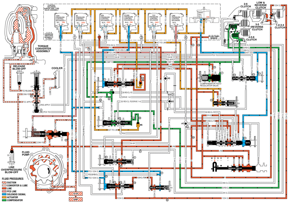
low reverse clutch iii pressure pressure or: n.h nh on nl or: nh. clutch clutch mass: tofioue converter assemblv pcstcc release blow-off compensator feed unv fd tcdapplv 456 cl 25 cl cl sol line ovefipfiessufie blow-off fluid pressures suction converter lube line pcs line solenoid actuator compensator
 Cleanliness and Care
An automobile engine is a combination of many machined, honed, polished, and
lapped surfaces with tolerances that are measured in ten thousandths of an inch.
When any internal engine parts are ser ...
 Drive Range, First Gear Engine Braking (Gen 2)
Note: Some models of the 6T30/40/45/50 automatic transmission are equipped with
an electric auxiliary fluid pump for use in hybrid vehicles (BAS+). Hybrid vehicles
do not require internal combusti ...
Other materials:
Front Floor Console Replacement
Front Floor Console Replacement
Callout
Component Name
Preliminary Procedures
Remove the right and left front floor console extensions. Refer
to Front Floor Console Extension Replacement - Right Side and Front
Floor Conso ...
Rear Brake Caliper Bracket Replacement
Removal Procedure
Warning: Refer to Brake Dust Warning.
Raise and support the vehicle. Refer to Lifting and Jacking the Vehicle.
Remove the tire and wheel assembly. Refer to Tire and Wheel Removal
and Installation.
Note:
DO NOT use any ai ...
Intake Manifold Replacement (LDE)
Removal Procedure
Disconnect the negative battery cable. Refer to Battery Negative Cable
Disconnection and Connection.
Remove the throttle body assembly. Refer to Throttle Body Assembly Replacement.
Disconnect wiring harness plug.
Disconnect the pipes from ...

0.006