Chevrolet Sonic Owner's Manual: Steps for Determining Correct Load Limit
1. Locate the statement "The combined weight of occupants and cargo should never exceed XXX kg or XXX lbs." on your vehicle’s placard.
2. Determine the combined weight of the driver and passengers that will be riding in your vehicle.
3. Subtract the combined weight of the driver and passengers from XXX kg or XXX lbs.
4. The resulting figure equals the available amount of cargo and luggage load capacity. For example, if the "XXX" amount equals 1400 lbs. and there will be five 150 lb passengers in your vehicle, the amount of available cargo and luggage load capacity is 650 lbs. (1400-750 (5 x 150) = 650 lbs.) 5. Determine the combined weight of luggage and cargo being loaded on the vehicle. That weight may not safely exceed the available cargo and luggage load capacity calculated in Step 4.
6. If your vehicle will be towing a trailer, load from your trailer will be transferred to your vehicle. Consult this manual to determine how this reduces the available cargo and luggage load capacity of your vehicle.”
This vehicle is neither designed nor intended to tow a trailer.

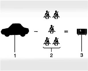
Example 1
1. Vehicle Capacity Weight for Example 1 = 453 kg (1,000 lbs).
2. Subtract Occupant Weight @ 68 kg (150 lbs) × 2 = 136 kg (300 lbs).
3. Available Occupant and Cargo Weight = 317 kg (700 lbs).

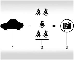
Example 2
1. Vehicle Capacity Weight for Example 2 = 453 kg (1,000 lbs).
2. Subtract Occupant Weight @ 68 kg (150 lbs) × 5 = 340 kg (750 lbs).
3. Available Cargo Weight = 113 kg (250 lbs).

Example 3
1. Vehicle Capacity Weight for Example 3 = 453 kg (1,000 lbs).
2. Subtract Occupant Weight @ 91 kg (200 lbs) × 5 = 453 kg (1,000 lbs).
3. Available Cargo Weight = 0 kg (0 lbs).
Refer to the vehicle's Tire and Loading Information label for specific information about the vehicle's capacity weight and seating positions. The combined weight of the driver, passengers, and cargo should never exceed the vehicle's capacity weight.
 Tire and Loading Information Label
A vehicle-specific Tire and Loading Information label is attached to the vehicle's
center pillar (B-pillar). The Tire and Loading Information label shows the number
of occupant seating posit ...
 Certification Label
Label Example
A vehicle-specific Certification label is attached to the vehicle's center pillar
(B-pillar). The label tells the gross weight capacity of the vehicle, called the
Gross Vehicl ...
Other materials:
Replacing Safety Belt System Parts after a Crash
Warning: A crash can damage the safety belt system in the vehicle.
A damaged safety belt system may not properly protect the person using it, resulting
in serious injury or even death in a crash. To help make sure the safety belt
systems are working properly after a crash, have them insp ...
Seat Adjustment
Manual Seats
Warning: You can lose control of the vehicle if you try to adjust
a driver seat while the vehicle is moving. Adjust the driver seat only when
the vehicle is not moving.
To adjust a manual seat:
Pull the handle at the front of the seat.
Slide the ...
Drive Range, Fifth Gear (Gen 2)
As vehicle speed increases, the transmission control module (TCM) processes input
signals from the automatic transmission input and output speed sensors, the throttle
position sensor and other vehicle sensors to determine the precise moment to command
ON the normally-low 35R pressure control s ...
0.0049
