Chevrolet Sonic Repair Manual: 3-5-Reverse and 4-5-6 Clutch Housing Assemble (6T30/40/45/50 - Gen 2)
| Table 1: | 4?? Clutch Piston Installation |
| Table 2: | 4?? Clutch Fluid Dam Installation |
| Table 3: | 3? Reverse Clutch Plates Installation |
| Table 4: | Reluctor Wheel and Piston Installation |
| Table 5: | 4?? Clutch Plates Installation |
| Table 6: | Turbine Shaft Installation |
- 4?? Clutch Piston Installation
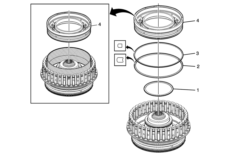
4?? Clutch Piston Installation Callout
Component Name
1
4?? Clutch Piston Inner Seal
2
4?? Clutch Piston Outer Seal (Large) (Rounded)
3
4?? Clutch Piston Outer Seal (Dark Blue) (Stepped)
4
4?? Clutch Piston
Special ToolsNote:
- DT-47805 seal protector prevents the piston seal lip from damage during installation. Apply a thin coat of ATF to the I.D. of DT-47805 seal protector to ease the installation of the piston.
- DT-47951-2 spring compressor can be used as a pusher if necessary.
- DT-47805 Seal Protector
- DT-47951-2 Spring Compressor
For equivalent regional tools, refer to Special Tools.
- 4?? Clutch Fluid Dam Installation
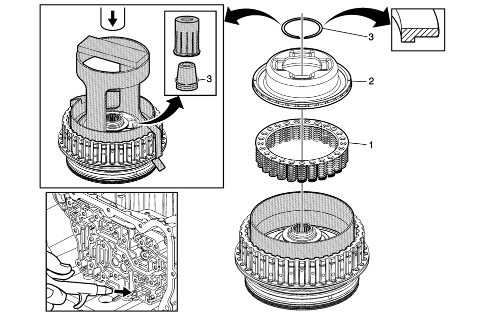
4?? Clutch Fluid Dam Installation Callout
Component Name
1
4?? Clutch Piston Return Spring Assembly
2
4?? Clutch Piston Fluid Dam Assembly
Special ToolsNote:
The seal protector prevents the dam seal lip from damage during installation. Apply a thin coat of ATF to the I.D. of the seal protector to ease the installation of the dam.
- DT-47951-1 Seal Protector for 6T40/45 applications
- DT-50117 Seal Protector for 6T50 applications
For equivalent regional tools, refer to Special Tools.
3
4?? Clutch Dam Retaining Ring
ProcedureCaution:
Regulate the air pressure to 276 kPa (40 psi) maximum. High pressure could cause the piston to over travel and damage the piston seals.
- Leave the seal protector on the clutch housing while installing the retaining ring. Install the dam retainer clips DT 50117-1 seal protector to hold the seal protector in place.
- Use DT 46620-2 retaining clips and DT 50573 ring guide to install a NEW 4-5-6 clutch dam retaining ring. Assemble the ring ??leg facing down, DT 50573 and DT 46620 and insert as an assembly onto the clutch hub to install the ring.
- Place the housing assembly onto the input shaft support inside the case. Apply shop air to the clutch fluid feed hole in the case to verify proper piston operation.
- DT-47951-2 Spring Compressor
- DT 46620 Seal Installer
- DT 50117-1 Seal Protector
- DT 50117-2 Seal Protector Retaining Clips
- DT 50573 Retaining Ring Installer
For equivalent regional tools, refer to Special Tools.
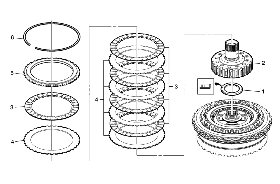
- 3? Reverse Clutch Plates Installation
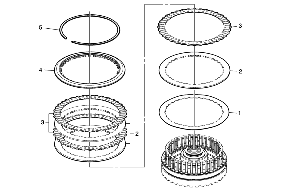
3? Reverse Clutch Plates Installation Callout
Component Name
1
3? Reverse Clutch Apply Plate (Waved)
2
3? Reverse Clutch Plate (Qty: 3)
3
3? Reverse Clutch Plate Assembly (Qty: 3)
4
3? Reverse Clutch Backing Plate
5
3? Reverse Clutch Backing Plate Ring Retainer Ring
- Reluctor Wheel and Piston Installation
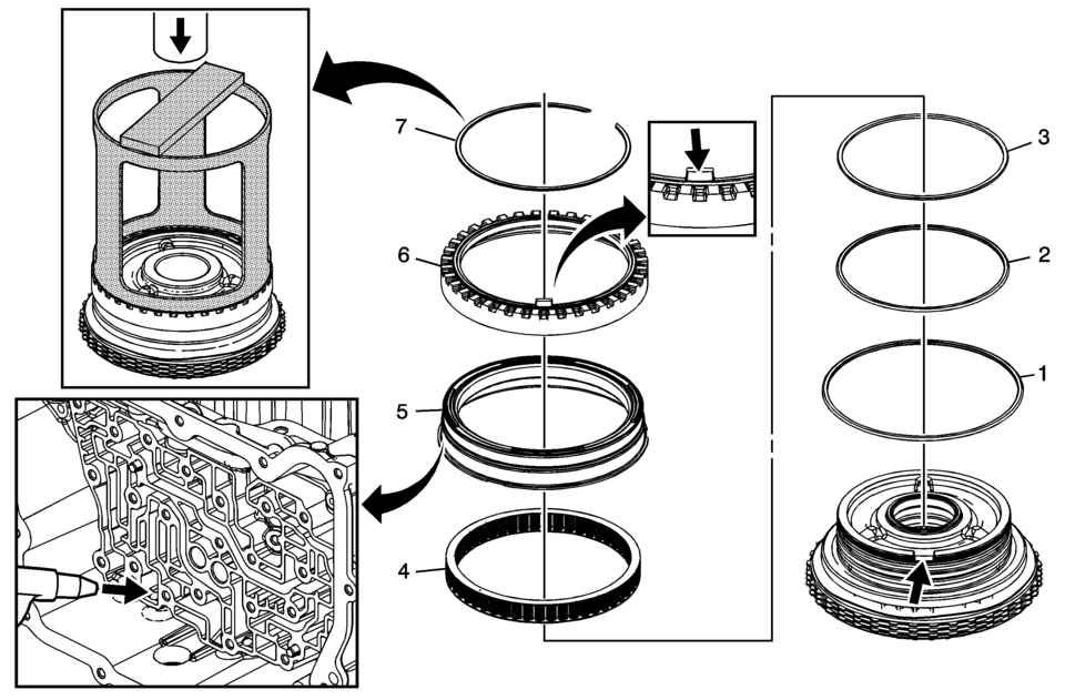
Reluctor Wheel and Piston Installation Callout
Component Name
1
3? Reverse Clutch Piston Dam Seal (Black)
2
3? Reverse Clutch Piston Inner Seal
3
3? Reverse Clutch Piston Inner (Reluctor) Seal (Orange)
4
3? Reverse Clutch Piston Return Spring Assembly
5
3? Reverse Clutch Piston
6
Input Shaft Speed Sensor Reluctor Wheel
7
Input Shaft Speed Sensor Reluctor Ring Retainer Ring
Caution:
Compress the reluctor wheel just enough to clear the retainer. Over compressing the reluctor wheel will break the alignment tab and the clutch housing.
Caution:
Regulate the air pressure to 276 kPa (40 psi) maximum. High pressure could cause the piston to over travel and damage the piston seals.
Procedure
Place the housing assembly onto the input shaft support inside the case. Apply shop air to the clutch fluid feed hole in the case to verify proper piston operation.
Special Tools
DT-47694 Piston Spring Compressor
For equivalent regional tools, refer to Special Tools.
- 4?? Clutch Plates Installation
4?? Clutch Plates Installation Callout
Component Name
1
Reaction Carrier Hub Thrust Bearing Assembly
2
Reaction Carrier Hub Assembly
3
4?? Clutch Plate Assembly (Qty: 5)
4
4?? Clutch Plate (Qty: 5)
5
4?? Clutch Backing Plate
6
4?? Clutch Backing Plate Retaining Ring
- Turbine Shaft Installation
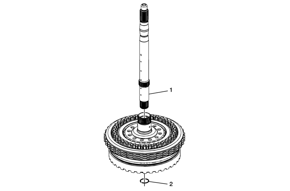
Turbine Shaft Installation Callout
Component Name
1
Turbine Shaft
2
Turbine Shaft Retainer Ring
Note:
Do not re-use the turbine shaft retainer ring.
Special Tools
GE 5586-A Snap Ring Pliers or equivalent
For equivalent regional tools, refer to Special Tools.
 3-5-Reverse and 4-5-6 Clutch Fluid Seal Ring Replacement (Gen 2)
3-5-Reverse and 4-5-6 Clutch Fluid Seal Ring Replacement
Callout
Component Name
Special Tools
DT-46620 Seal Installer
For e ...
 3-5-Reverse and 4-5-6 Clutch Housing Disassemble (6T30/40/45/50 - Gen 2)
Table 1:
Turbine Shaft, Reluctor Wheel and Piston Removal
Table 2:
4?? Clutch Plate Removal
Table 3:
4?? Clutch Piston Removal
Table 4:
Reluctor Wheel ...
Other materials:
Radio Windshield Side Garnish Molding Speaker Replacement
Radio Windshield Side Garnish Molding Speaker Replacement
Callout
Component Name
Preliminary Procedure
Remove the windshield side garnish molding. Refer to
Windshield Side Garnish Molding Replacement.
1
...
Service Prior to Assembly
The importance of cleanliness during assembly cannot be overstated. Dirt or debris
will cause engine damage. An automobile engine is a combination of many machined,
honed, polished and lapped surfaces with minor tolerances. When any internal engine
parts are serviced, care and cleanliness are ...
Transmission Case Assemble (Gen 1)
Special Tools
3-9506289 Universal Adapter
J-840733 Driver
R-0007758 Holding Fixture
R-0007761 Universal Handle
R-0007770 Holding Fixture Adapter Plates
T-9804669 Seal Installer
T-0307000 Extractor and Driver Fixture
For equivalent regional tools, refer to Special Tools.
...

0.0072