Chevrolet Sonic Repair Manual: Battery Positive and Negative Cable Replacement
- Removal Procedure
-
- Disconnect the negative battery cable. Refer to Battery Negative Cable Disconnection and Connection.
- Remove the fuse block and battery positive cable cover.
- Remove the battery tray. Refer to Battery Tray Replacement.
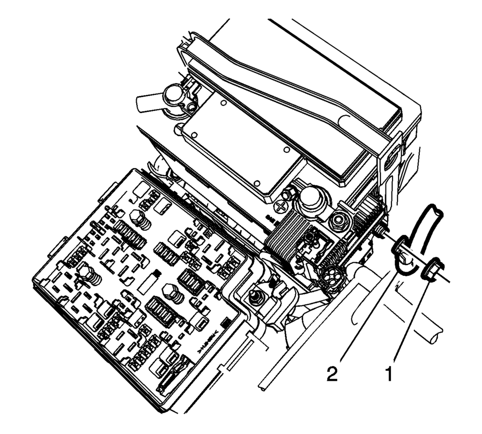
- Remove the battery positive nut (1) and the battery positive cable (2), from the battery positive cable junction block.
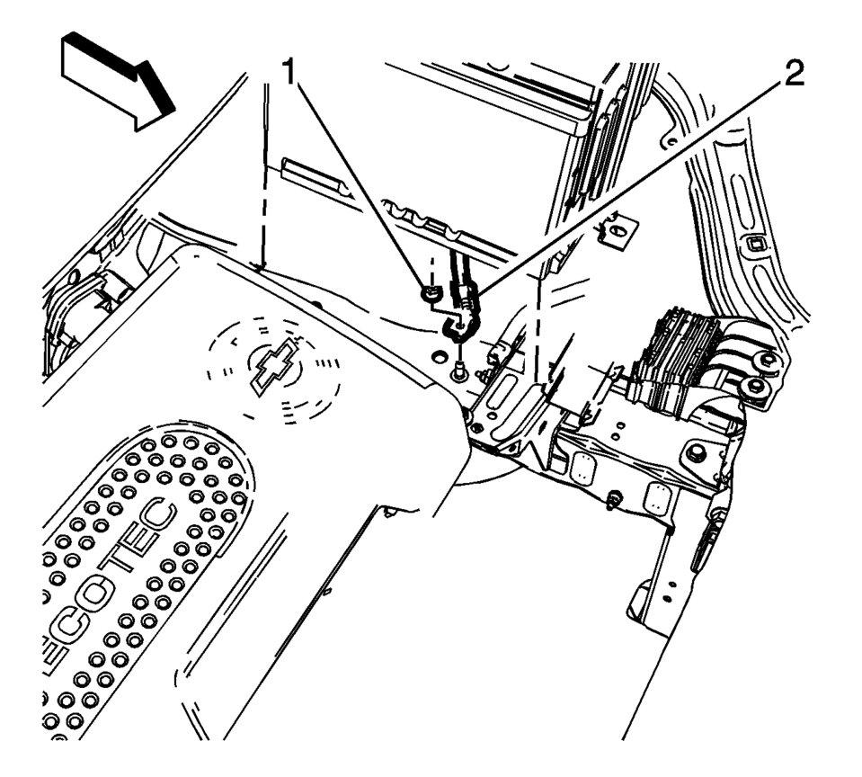
- Remove the battery negative cable nut (1) and the battery negative cable (2), from the chassis frame stud.
- Remove the drivetrain and front suspension frame skid plate. Refer to Drivetrain and Front Suspension Frame Skid Plate Replacement.
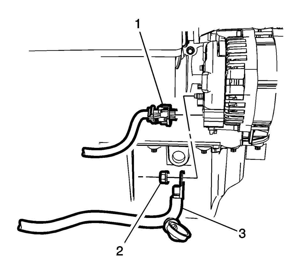
- Remove the battery positive cable nut (2) and the battery positive cable (3), from the back of the generator.
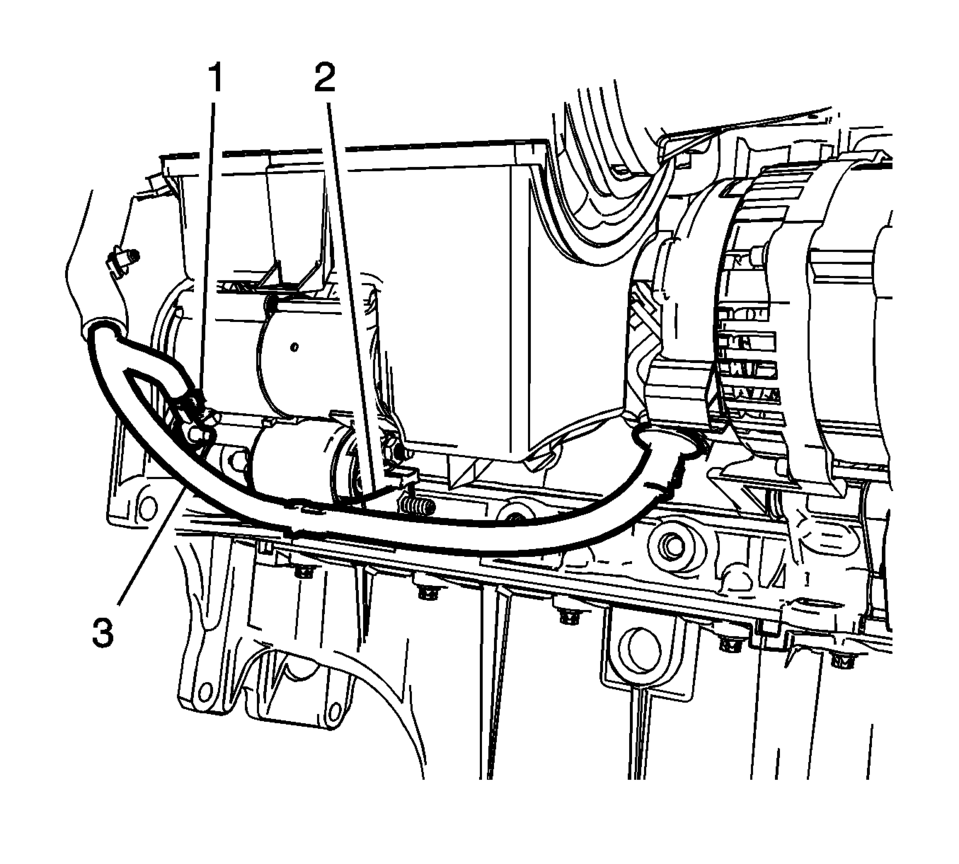
- Remove the battery negative cable stud/nut (1) and the starter solenoid nut (2).
- Remove the battery positive and negative cable (1) from the engine compartment.
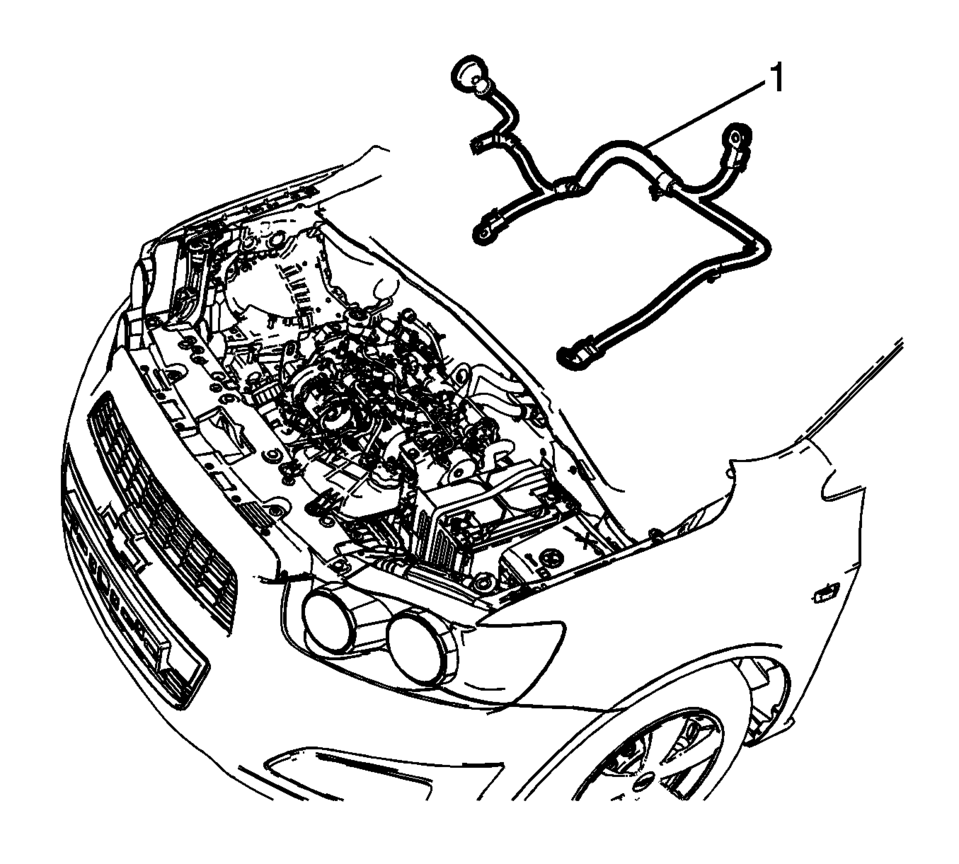
Note:
Visualize the routing of the battery positive and negative cable within the engine compartment.
- Installation Procedure
-
- Install the battery positive cable (3) to the back of the generator
and tighten nut (2) to 20 Y (15 lb ft)
.
- Install the battery positive cable (3) to the starter solenoid and tighten
nut (2) to 12 Y (9 lb ft)
.
- Install the battery negative cable to the starter and tighten the stud/nut (1)
to 25 Y (18 lb ft)
.
- Install the drivetrain and front suspension frame skid plate. Refer to Drivetrain and Front Suspension Frame Skid Plate Replacement.
- Install the battery negative cable nut (1) and the battery negative
cable (2), to the chassis frame stud and tighten to 22 Y (16 lb ft)
.
- Install the battery positive cable (2) to the battery positive cable
extension cable junction block and tighten nut (1) to 12 Y (9 lb ft)
.
- Install the battery tray. Refer to Battery Tray Replacement.
- Connect the negative battery cable. Refer to Battery Negative Cable Disconnection and Connection.
- Install the fuse block and battery positive cable cover.
Caution:
Refer to Fastener Caution.
- Install the battery positive cable (3) to the back of the generator
and tighten nut (2) to 20 Y (15 lb ft)
 Battery Positive Cable Replacement
Removal Procedure
Disconnect the negative battery cable. Refer to Battery Negative Cable
Disconnection and Connection.
Remove the underhood fuse block cover.
Remove the ...
 Battery Replacement
Removal Procedure
Open the hood.
Disconnect the negative battery cable. Refer to Battery Negative Cable
Disconnection and Connection.
Remove the battery retainer bo ...
Other materials:
Rear Side Door Window Weatherstrip Replacement (Hatchback)
Rear Side Door Window Weatherstrip Replacement
Callout
Component Name
Preliminary Procedure
Remove the rear side door window . Refer to Rear Side Door Window Replacement.
1
Rear Side Door Window ...
Data Link Communications Description and Operation
Note: This is an overview of different serial data buses used by GM
devices to communicate with each others. Use Data Communication Schematics to
find out which serial data buses are configured for a specific vehicle.
Circuit Description
There are many components in a vehicle t ...
Fuel Pressure Relief
Special Tools
EN-34730-91 Pressure Tester
For equivalent regional tools, refer to Special Tools.
Warning: Gasoline or gasoline vapors are highly flammable. A fire
could occur if an ignition source is present. Never drain or store gasoline
or diesel fuel in an open container, due ...

0.006