Chevrolet Sonic Repair Manual: Body Hinge Pillar Lower Reinforcement Replacement
- Removal Procedure
-
- Disable the SIR system. Refer to SIR Disabling and Enabling.
- Disconnect the negative battery cable. Refer to Battery Negative Cable Disconnection and Connection.
- Remove all related panels and components.
- Repair as much of the damage as possible. Refer to Dimensions - Body.
- Remove the sealers and anti-corrosion materials from the repair area. Refer to Anti-Corrosion Treatment and Repair.
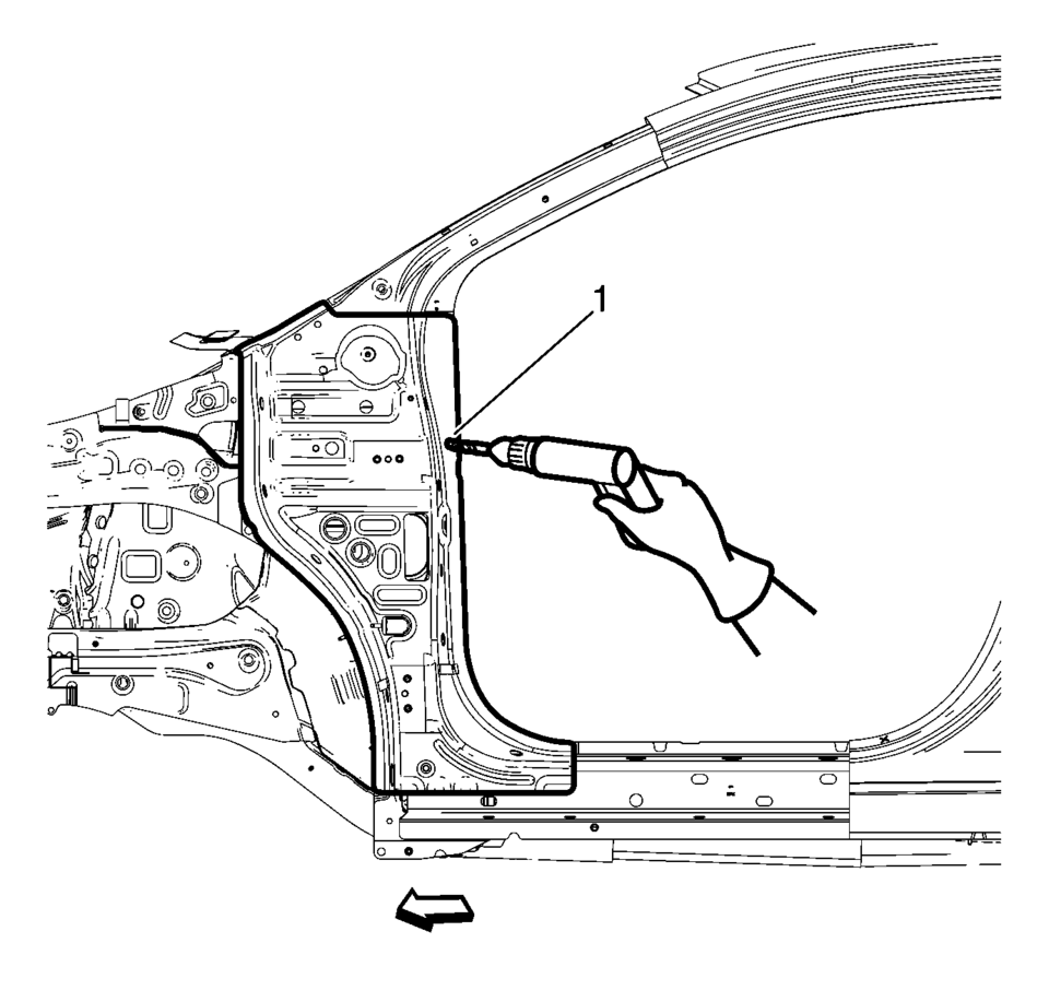
- Locate and mark all the necessary factory welds of the front hinge pillar body.
- Drill all factory welds (1). Note the number and location of welds for installation of the service assembly.
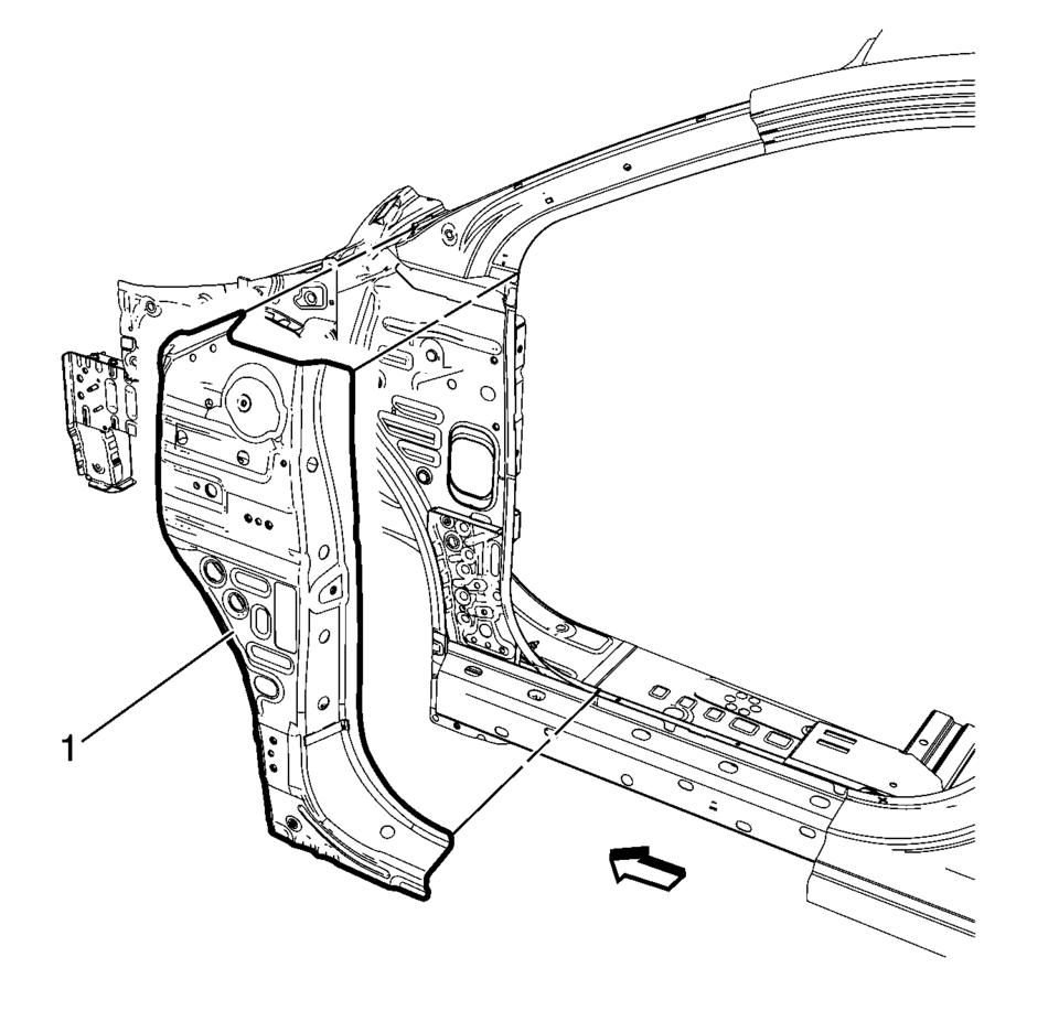
- Remove the damaged front hinge pillar body reinforcement (1).
Warning:
Refer to Approved Equipment for Collision Repair Warning.
- Installation Procedure
-
- Prepare all mating surfaces as necessary.
- Align the front hinge pillar body reinforcement.
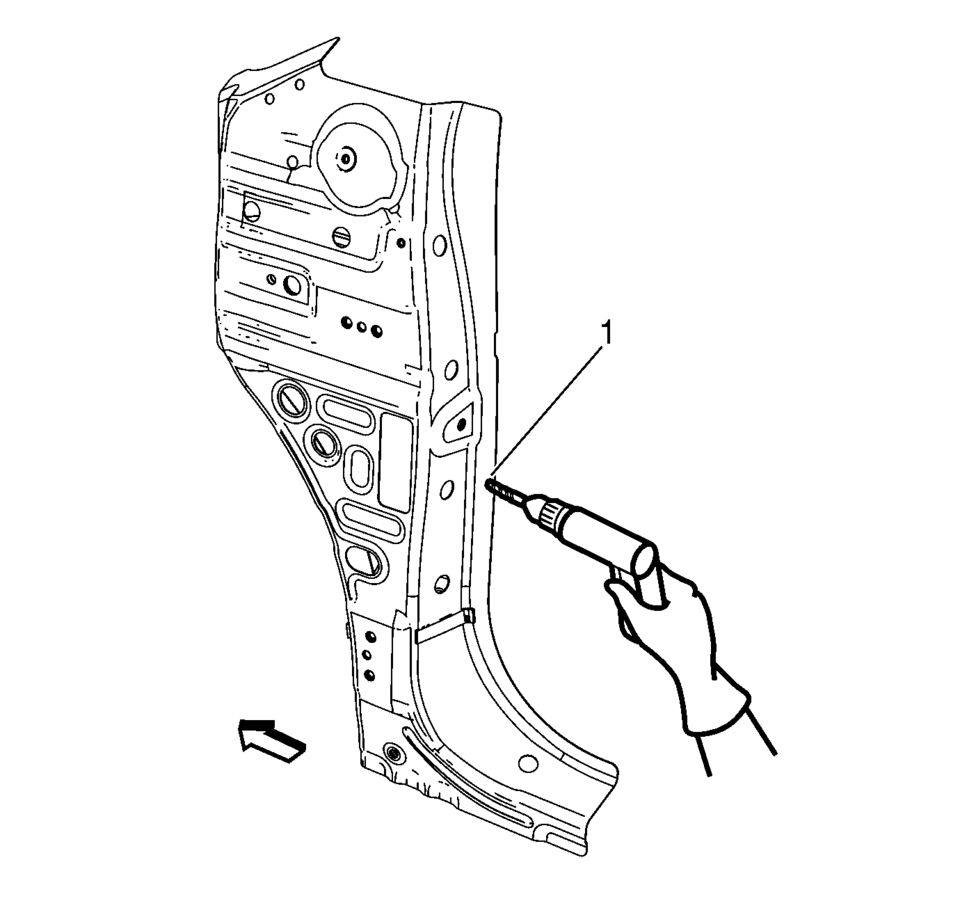
- Drill 8 mm (5/16 in)
holes for plug welding along the edges of the front hinge pillar body as noted from the original panel (1).
- Clean and prepare the attaching surfaces for welding.
- Position the front hinge pillar body reinforcement on the vehicle (1).
- Verify the fit of the front hinge pillar body reinforcement.
- Clamp the front hinge pillar body reinforcement into position.
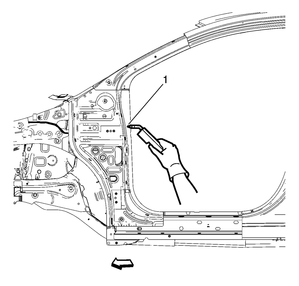
- Plug weld accordingly (1).
- Apply the sealers and anti-corrosion materials to the repair area, as necessary. Refer to Anti-Corrosion Treatment and Repair.
- Paint the repaired area. Refer to Basecoat/Clearcoat Paint Systems.
- Install all related panels and components.
- Connect the negative battery cable. Refer to Battery Negative Cable Disconnection and Connection.
- Enable the SIR system. Refer to SIR Disabling and Enabling.
 General
...
 Body Waterleak Repair
Warning: If the vehicle interior is exposed to moisture and becomes
soaked up to the level of the sensing and diagnostic module (SDM), the SDM and
SDM harness connector must be replaced. ...
Other materials:
Auxiliary Devices
The optional AUX input allows portable devices to connect to the vehicle using
the 3.5 mm(1/8 in) input jack. The AUX input jack, if equipped, is in the storage
area to the right of the infotainment system.
A second AUX input is on the front of the infotainment system, if equipped. See
Overvi ...
Engine Front Cover and Oil Pump Assemble
Oil Pump Installation
Note: The oil pump slide spring and pin, as well as the slide
seal and slide seal spring can be ordered as single parts. All other
oil pump components can only be ordered as a replacement kit.
Install the oil pump components in the fo ...
System temporarily unavailable
When any of the following messages appear on the vehicle information display,
a chime will sound and the I-BSI system will be turned off automatically.
"Unavailable Slippery Road": When the VDC system (except traction control
system function) or ABS operates.
"Currently Una ...

0.0051