Chevrolet Sonic Repair Manual: Body Side Frame Rocker Reinforcement Replacement
- Removal Procedure
-
- Disable the SIR system. Refer to SIR Disabling and Enabling.
- Disconnect the negative battery cable. Refer to Battery Negative Cable Disconnection and Connection.
- Remove all related panels and components.
- Repair as much of the damage as possible to factory specifications. Refer to Dimensions - Body.
- Remove the sealers and anti-corrosion materials from the repair area, as necessary. Refer to Anti-Corrosion Treatment and Repair.
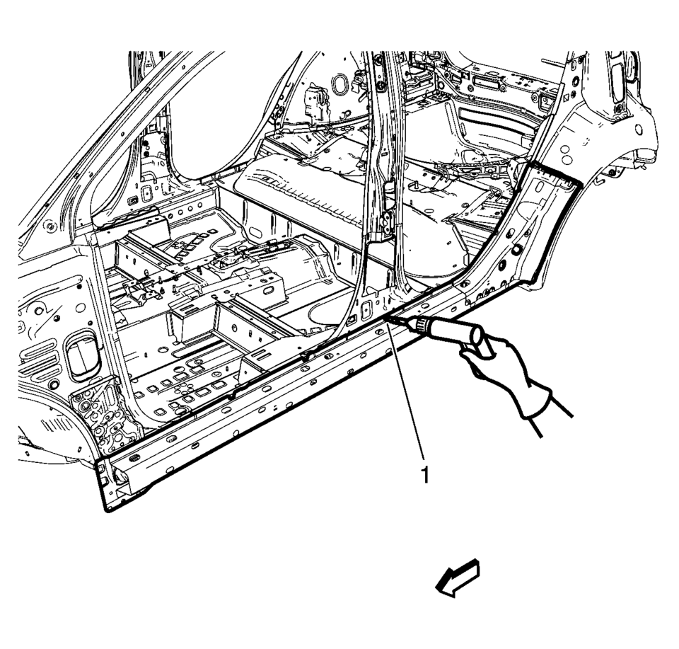
- Locate and mark all the necessary factory welds of the body side frame rocker reinforcement.
- Drill all factory welds (1). Note the number and location of welds for installation of the service assembly.
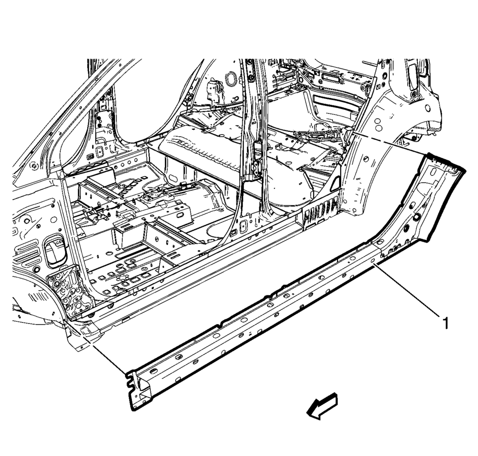
- Remove the damaged body side frame rocker reinforcement (1).
Warning:
Refer to Approved Equipment for Collision Repair Warning.
Warning:
Refer to Glass and Sheet Metal Handling Warning.
Note:
The body side frame rocker reinforcement is made of Ultra High Strength Dual Phase Steel and should be replaced only at factory joints. Repairing or sectioning of this part is not recommended. Refer to Ultra High Strength Dual Phase Steel.
..
- Installation Procedure
-
- Align the body side frame rocker reinforcement.
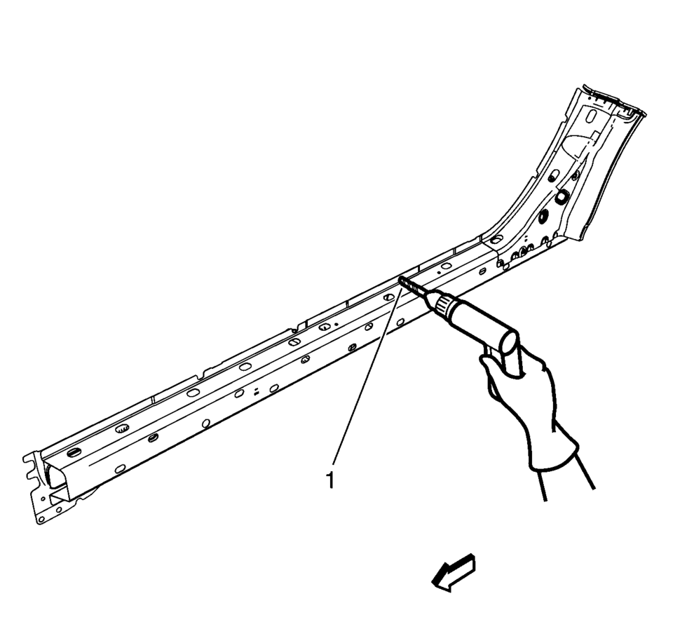
- Drill a 8?€‰mm (5/16?€‰in)
holes for plug welding along the edges of the quarter outer panel (1) as noted from the original panel.
- Clean and prepare the attaching surfaces for welding.
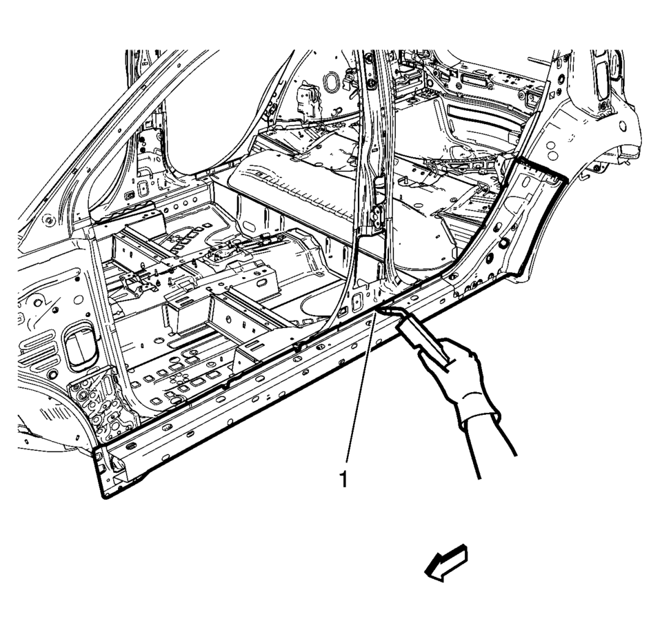
- Position the body side frame rocker reinforcement on the vehicle (1).
- Verify the fit of the body side frame rocker reinforcement.
- Clamp the body side frame rocker reinforcement into position.
- Plug the weld accordingly (1).
- Apply the sealers and anti-corrosion materials to the repair area, as necessary. Refer to Anti-Corrosion Treatment and Repair.
- Paint the repaired area. Refer to Basecoat/Clearcoat Paint Systems.
- Install all related panels and components.
- Connect the negative battery cable. Refer to Battery Negative Cable Disconnection and Connection.
- Enable the SIR system. Refer to SIR Disabling and Enabling.
(\ ..

 Driver or Passenger Seat Back Cushion Frame Replacement
Driver or Passenger Seat Back Cushion Frame Replacement
Callout
Component Name
Preliminary Procedures
Remove the driver or passenge ...
Other materials:
Rear Seat Cushion Removal and Installation
Rear Seat Cushion Removal and Installation
Callout
Component Name
1
Rear Seat Cushion Replacement
Procedure
Release the rear seat center seat belts.
Lift up on the front of the seat cushion at the latch locati ...
Heater Core Inlet Tube Replacement
Heater Core Inlet Tube Replacement
Callout
Component Name
Preliminary Procedures
Remove the Heater and Air Conditioning Evaporator and Blower Module.
Refer to Heater and Air Conditioning Evaporator and Blower Module Removal
...
Torque Converter Fluid Seal Replacement
Torque Converter Fluid Seal Replacement
Callout
Component Name
1
Torque Converter Fluid Seal Retainer
2
Torque Converter Fluid Seal
Special Tools
DT-47791-A Seal Installer
DT-6125- ...

0.0053