Chevrolet Sonic Repair Manual: Brake Rotor Assembled Lateral Runout Correction - Indexing
Special Tools
CH-45101-100 Conical Brake Rotor Washers
For equivalent regional tools, refer to Special Tools.
- Brake rotor thickness variation MUST be checked BEFORE checking for assembled lateral runout (LRO). Thickness variation exceeding the maximum acceptable level can cause brake pulsation. Refer to Brake Rotor Thickness Variation Measurement.
- Brake rotor assembled LRO exceeding the maximum allowable specification can cause thickness variation to develop in the brake rotor over time, usually between 4,800–11,300 km (3,000–7,000 mi). Refer to Brake Rotor Assembled Lateral Runout Measurement.
- Remove the CH-45101-100 conical brake rotor washers and the lug nuts that were installed during the assembled LRO measurement procedure.
- Inspect the mating surface of the hub/axle flange and the brake rotor to ensure that there are no foreign particles or debris remaining.
- Index the brake rotor in a different orientation to the hub/axle flange.
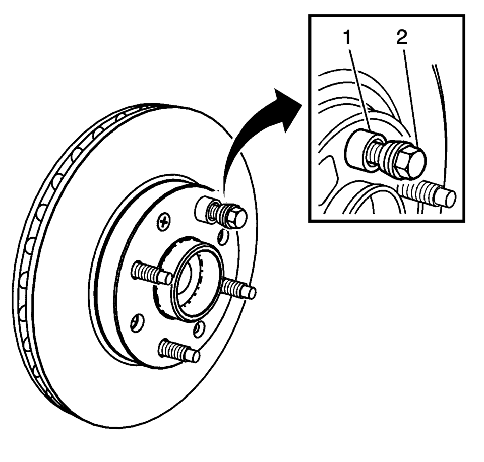
- Hold the rotor firmly in place against the hub/axle flange and install one of the CH-45101-100 conical brake rotor washers (1) and one lug nut (2) onto the upper-most wheel stud.
- Continue to hold the rotor secure and tighten the lug nut firmly by hand.
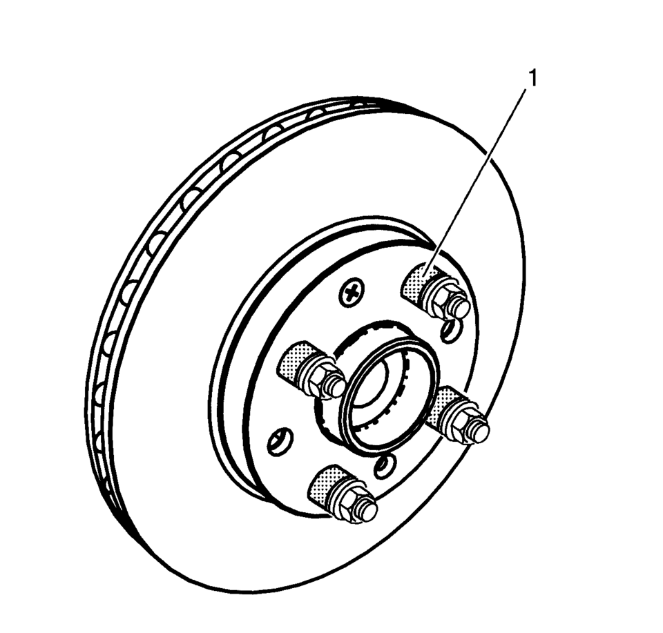
- Install the remaining CH-45101-100 conical brake rotor washers and lug nuts onto the wheel studs (1) and tighten the nuts firmly by hand in the tightening sequence.
- Tighten the lug nuts in sequence, in order to properly secure the rotor. Refer to Tire and Wheel Removal and Installation.
- Measure the assembled LRO of the brake rotor. Refer to Brake Rotor Assembled Lateral Runout Measurement.
- Compare the amount of change between this measurement and the original measurement.
- If this measurement is within specifications, proceed to step 14.
- If this measurement still exceeds specifications, repeat steps 1–9 until the best assembled LRO measurement is obtained.
- Matchmark the final location of the rotor to the wheel studs if the orientation is different than it was originally.
- If the brake rotor assembled LRO measurement still exceeds the maximum allowable specification, refer to Brake Rotor Assembled Lateral Runout Correction.
- If the brake rotor assembled LRO is within specification, install the brake caliper and depress the brake pedal several times to secure the rotor in place before removing the CH-45101-100 conical brake rotor washers and the lug nuts.
Warning:
Refer to Brake Dust Warning.
Note:
 Brake Rotor Assembled Lateral Runout Correction
Note:
Brake rotor thickness variation MUST be checked BEFORE checking for
assembled lateral runout (LRO). Thickness variation exceeding the maximum
acceptable level can cause brake p ...
 Brake Rotor Assembled Lateral Runout Correction - On Vehicle Lathe
Special Tools
CH-45101-100 Conical Brake Rotor Washers
For equivalent regional tools, refer to Special Tools.
Warning: Refer to Brake Dust Warning.
Note:
Brake rotor th ...
Other materials:
Lane Departure Warning (LDW)
For vehicles with this feature, read the entire section before using it.
Warning
The LDW system is an aid to help the vehicle stay in the driving lane. It
does not steer the vehicle. The LDW system may not:
. Provide enough time to avoid a crash.
. Detect lane markings under bad weather co ...
Taillamps, Turn Signal, Stoplamps, and Back-Up Lamps
Sedan Taillamp Shown, Hatchback Taillamp Similar
1. Back-up Lamp
2. Turn Signal Lamp
3. Stop Lamp/Taillamp
4. Sidemarker Lamp
To replace one of these bulbs:
1. Open the trunk.
2. Remove the two screws, which secure the taillamp assembly.
3. Remove the taillamp assembly by pulling it stra ...
Wiper and washer switch
Basic information
WARNING
In the Nissan Armada, using the washer system in freezing temperatures may
cause the fluid to freeze on the windshield, significantly reducing visibility.
Always warm the glass using the defroster before activating the washer system to
ensure safe driving conditions ...

0.0288