Chevrolet Sonic Repair Manual: Brake Rotor Assembled Lateral Runout Measurement
Special Tools
- CH-41013 Rotor Surfacing Kit
- CH-42450-A Wheel Hub Resurfacing Kit
- CH-45101 Hub and Wheel Runout Gauge
- CH-45101-100 Conical Brake Rotor Washers
For equivalent regional tools, refer to Special Tools.
- Brake rotor assembled lateral runout (LRO) exceeding the maximum allowable specification can cause thickness variation to develop in the brake rotor over time, usually between 4,800–11,300 km (3,000–7,000 mi).
- Brake rotor thickness variation MUST be inspected BEFORE inspecting for assembled lateral runout (LRO). Thickness variation exceeding the maximum acceptable level can cause brake pulsation. Refer to Brake Rotor Thickness Variation Measurement.
- Matchmark the position of the brake rotor to the wheel studs if this has not been done already.
- Inspect the mating surface of the hub/axle flange and the brake rotor to make sure that there are no foreign particles, corrosion, rust, or debris remaining. If the wheel hub/axle flange and/or brake rotor mating surfaces exhibit these conditions, perform the following steps:
- Remove the brake rotor from the vehicle. Refer to Front Brake Rotor Replacement.
- Using the CH-42450-A wheel hub resurfacing kit , thoroughly clean any rust or corrosion from the mating surface of the hub/axle flange.
- Using the CH-41013 rotor resurfacing kit , thoroughly clean any rust or corrosion from the mating surface of the brake rotor.
- Clean the friction surfaces of the brake rotor with denatured alcohol, or an equivalent approved brake cleaner.
- Install the rotor to the hub/axle flange using the matchmark made prior to removal.
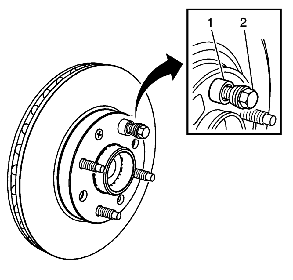
- Hold the brake rotor firmly in place against the hub/axle flange and install one of the CH-45101-100 conical brake rotor washers (1), and one lug nut (2) onto the upper-most wheel stud.
- Continue to hold the brake rotor secure and tighten the lug nut firmly by hand.
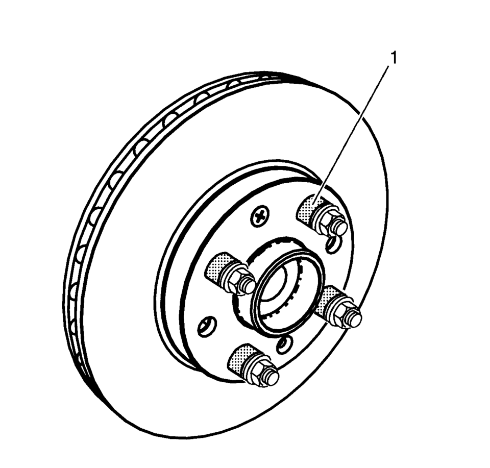
- Install the remaining CH-45101-100 conical brake rotor washers (1) and lug nuts onto the wheel studs and tighten the nuts firmly by hand in the tightening sequence.
- Tighten the lug nuts in sequence, in order to properly secure the rotor. Refer to Tire and Wheel Removal and Installation.
- If the brake rotor has been REFINISHED or REPLACED with a new rotor, proceed to step 14.
- If the brake rotor meets the following criteria, proceed to step 10.
Warning:
Refer to Brake Dust Warning.
Note:
Note:
Whenever the brake rotor has been separated from the hub/axle flange, any rust or contaminants should be cleaned from the hub/axle flange and the brake rotor mating surfaces. Failure to do this may result in excessive assembled lateral runout (LRO) of the brake rotor, which could lead to brake pulsation.
- The rotor is within specifications and is being REUSED.
- The rotor has NOT been refinished.
- The rotor does not exhibit thickness variation exceeding the maximum allowable level.

- Rotate the rotor until the lowest reading is displayed on the indicator dial, then set the dial to zero.
- Rotate the rotor until the highest reading is displayed on the dial.
- Mark the location of the high spot relative to the nearest wheel stud, or studs.
- Measure and record the amount of assembled LRO.
Front brake rotor maximum allowable assembled lateral runout: 0.05 mm (0.002 in)
If the brake rotor assembled LRO exceeds the specification, refinish the rotor to ensure true parallelism. Refer to Brake Rotor Refinishing. After refinishing the rotor, proceed to step 14.
- Rotate the rotor until the lowest reading is displayed on the indicator dial, then set the dial to zero.
- Rotate the rotor until the highest reading is displayed on the dial.
- Mark the location of the high spot relative to the nearest wheel stud, or studs.
- Measure and record the amount of assembled LRO.
Front brake rotor maximum allowable assembled lateral runout: 0.05 mm (0.002 in)
.
 Brake Rotor Assembled Lateral Runout Correction - On Vehicle Lathe
Special Tools
CH-45101-100 Conical Brake Rotor Washers
For equivalent regional tools, refer to Special Tools.
Warning: Refer to Brake Dust Warning.
Note:
Brake rotor th ...
 Brake Rotor Refinishing
Special Tools
CH-41013 Rotor Resurfacing Kit
CH-42450-A Wheel Hub Resurfacing Kit
For equivalent regional tools, refer to Special Tools.
Warning: Refer to Brake Dust Warning.
Note ...
Other materials:
Brake Assist
This vehicle has a brake assist feature designed to assist the driver in stopping
or decreasing vehicle speed in emergency driving conditions. This feature automatically
uses the stability system hydraulic brake control module to supplement the power
brake system under conditions where the dri ...
Removing the Flat Tire and Installing the Spare Tire
1. Do a safety check before proceeding. See If a Tire Goes Flat.
2. Remove the wheel cover, if the vehicle has one, to reach the wheel bolts.
3. Turn the wheel nuts counterclockwise to loosen them. Do not remove them yet.
4. Place the jack at the position marked with a half circle.
5. In ...
Fuel and Evaporative Emission Pipe Warning
Warning: In order to reduce the risk of fire and personal injury observe
the following items:
Replace all nylon fuel pipes that are nicked, scratched or damaged during
installation, do not attempt to repair the sections of the nylon fuel pipes
Do not hammer directly on the fu ...

0.0054