
Chevrolet Sonic Owner's Manual: Brake System Warning Light
The vehicle brake system consists of two hydraulic circuits. If one circuit is not working, the remaining circuit can still work to stop the vehicle. For normal braking performance, both circuits need to be working
If the warning light comes on, there is a brake problem. Have the brake system inspected right away.
Warning
The brake system might not be working properly if the brake system warning light is on. Driving with the brake system warning light on can lead to a crash. If the light is still on after the vehicle has been pulled off the road and carefully stopped, have the vehicle towed for service.
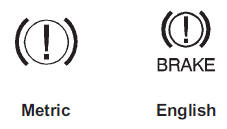
This light should come on briefly when the ignition is turned to ON. If it does not come on then, have it fixed so it will be ready to warn if there is a problem.
When the ignition is on, the brake system warning light will also come on when the parking brake is set. The light will stay on if the parking brake does not fully release. If it stays on after the parking brake is fully released, it means there is a brake problem.
If the light comes on while driving, carefully pull off the road and stop. The pedal may be harder to push or may go closer to the floor. It may take longer to stop. If the light is still on, have the vehicle towed for service. See Towing the Vehicle.
 Service Vehicle Soon Light
For vehicles with this light, it comes on if a condition exists that may require
the vehicle to be taken in for service.
If the light comes on, take the vehicle to your dealer for service as soon ...
 Antilock Brake System (ABS) Warning Light
This light comes on briefly when the engine is started.
If the light stays on, turn the ignition to LOCK/OFF or if the light comes on,
stop as soon as possible and turn the ignition off. Then sta ...
Other materials:
Safety System Check
Now and then, check that the safety belt reminder light, safety belts, buckles,
latch plates, retractors, and anchorages are all working properly. Look for any
other loose or damaged safety belt system parts that might keep a safety belt system
from doing its job. See your dealer to have it re ...
Lane Departure Warning (LDW)
For vehicles with this feature, read the entire section before using it.
Warning
The LDW system is an aid to help the vehicle stay in the driving lane. It
does not steer the vehicle. The LDW system may not:
. Provide enough time to avoid a crash.
. Detect lane markings under bad weather co ...
Odor Correction
Eliminating Air Conditioning Odor
Odors may be emitted from the air conditioning system primarily at start
up in hot, humid climates. The following conditions may cause the odor:
Debris is present in the HVAC module.
Microbial growth on the evaporator core
When the blower ...

0.0054