Chevrolet Sonic Repair Manual: Camshaft Sprocket Replacement
Special Tools
- EN-6340 Camshaft Adjuster Locking Tool
- EN-6628–A Camshaft Locking Tool
- EN-45059 Angle Meter
For equivalent regional tools, refer to Special Tools.
- Removal Procedure
-
- Open the hood.
- Remove the air cleaner housing. Refer to Air Cleaner Assembly Replacement.
- Remove the camshaft cover. Refer to Camshaft Cover Replacement.
- Remove the drive belt tensioner. Refer to Drive Belt Tensioner Replacement.
- Remove the timing belt. Refer to Timing Belt Replacement.
- Remove the timing belt idler pulley. Refer to Timing Belt Idler Pulley Removal.
- Set the crankshaft in direction of engine rotation to 60°
(a) before TDC. Use the EN-45059 meter and the crankshaft balancer bolt.
- Remove the crankshaft sprocket. Refer to Crankshaft Sprocket Removal.
- Lower the vehicle.
- Remove the engine mount bracket. Refer to Engine Mount Bracket Replacement.
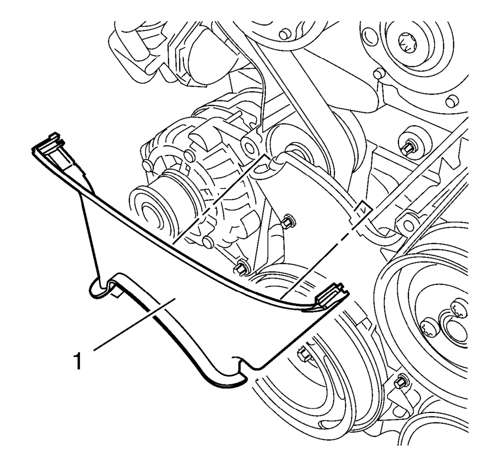
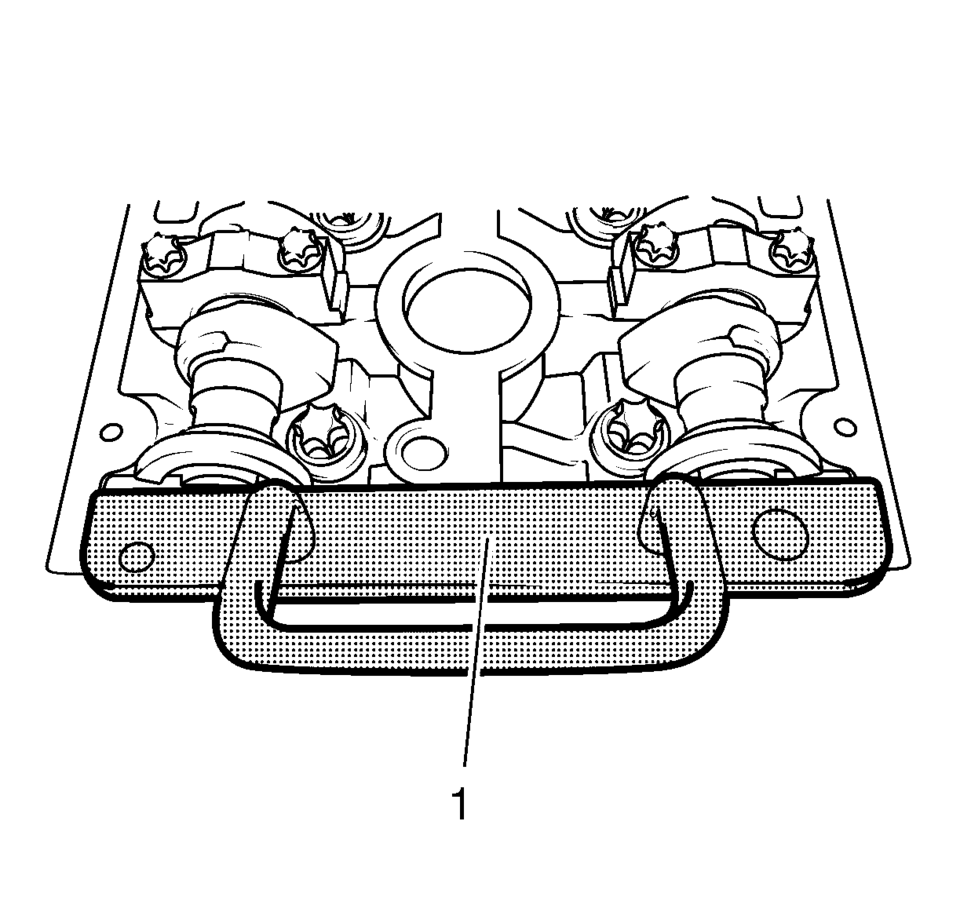
- Remove the center front timing belt cover from the rear timing belt cover at 2 locations.
- Remove the center front timing belt cover (1).
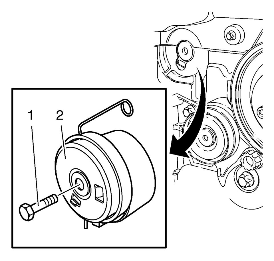
- Remove the tensioner bolt (1).
- Remove the timing belt tensioner (2).
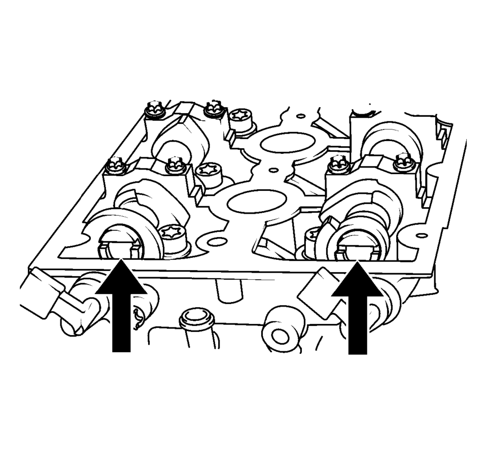
- Turn the camshaft by the hexagon until the groove on the end of the camshafts is horizontal.
- Install the EN-6628–A locking tool (1).
- Raise and support the vehicle. Refer to Lifting and Jacking the Vehicle.
- Place a collecting basin underneath the vehicle.
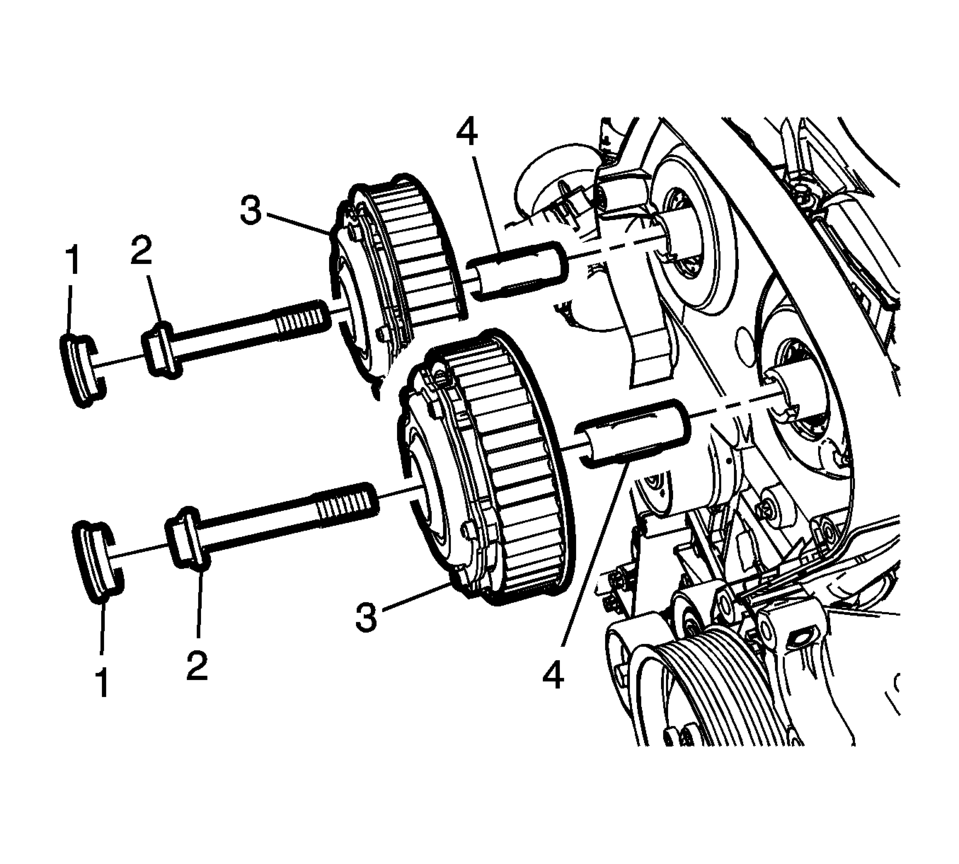
- Remove the camshaft position actuator adjuster closure bolt (1) of the intake camshaft position actuator adjuster and/or the exhaust camshaft position actuator adjuster (3).
- Remove and DISCARD the intake camshaft position actuator adjuster bolt and/or the exhaust camshaft position actuator adjuster bolt (2).
- Remove the intake camshaft position actuator adjuster and/or the exhaust camshaft position actuator adjuster (3) With Sleeve (4).
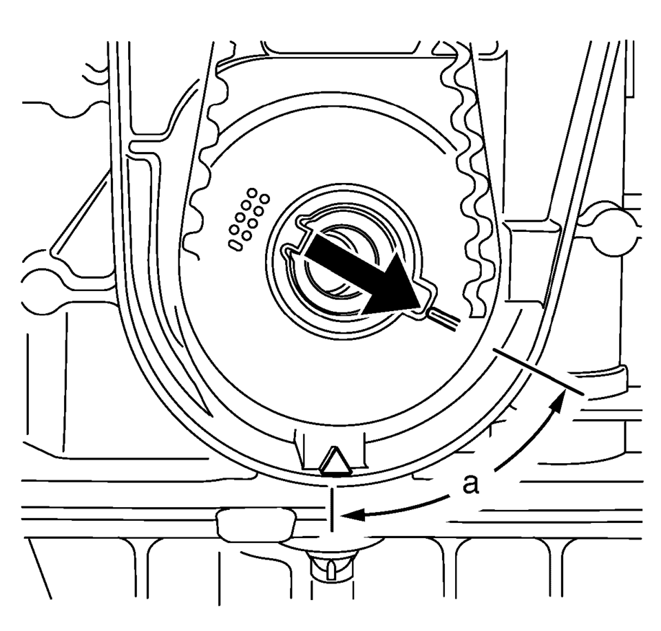
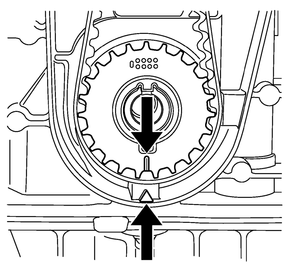
Note:
Note the arrows.
Note:
Some engine oil will run out of the camshaft and the camshaft position actuator adjuster. That is the reason for the removal of the whole timing assembly.
Note:
A second person is required. Counterhold against the hexagon of corresponding camshaft with an open-ended wrench.
- Installation Procedure
-
- Install intake camshaft position actuator adjuster and/or the exhaust camshaft position actuator adjuster (3) with sleeve (4).
- Install a NEW intake camshaft position actuator adjuster bolt and/or a NEW exhaust camshaft position actuator adjuster bolt (2).
- Install the EN-6340 locking tool into the camshaft position actuator adjusters.
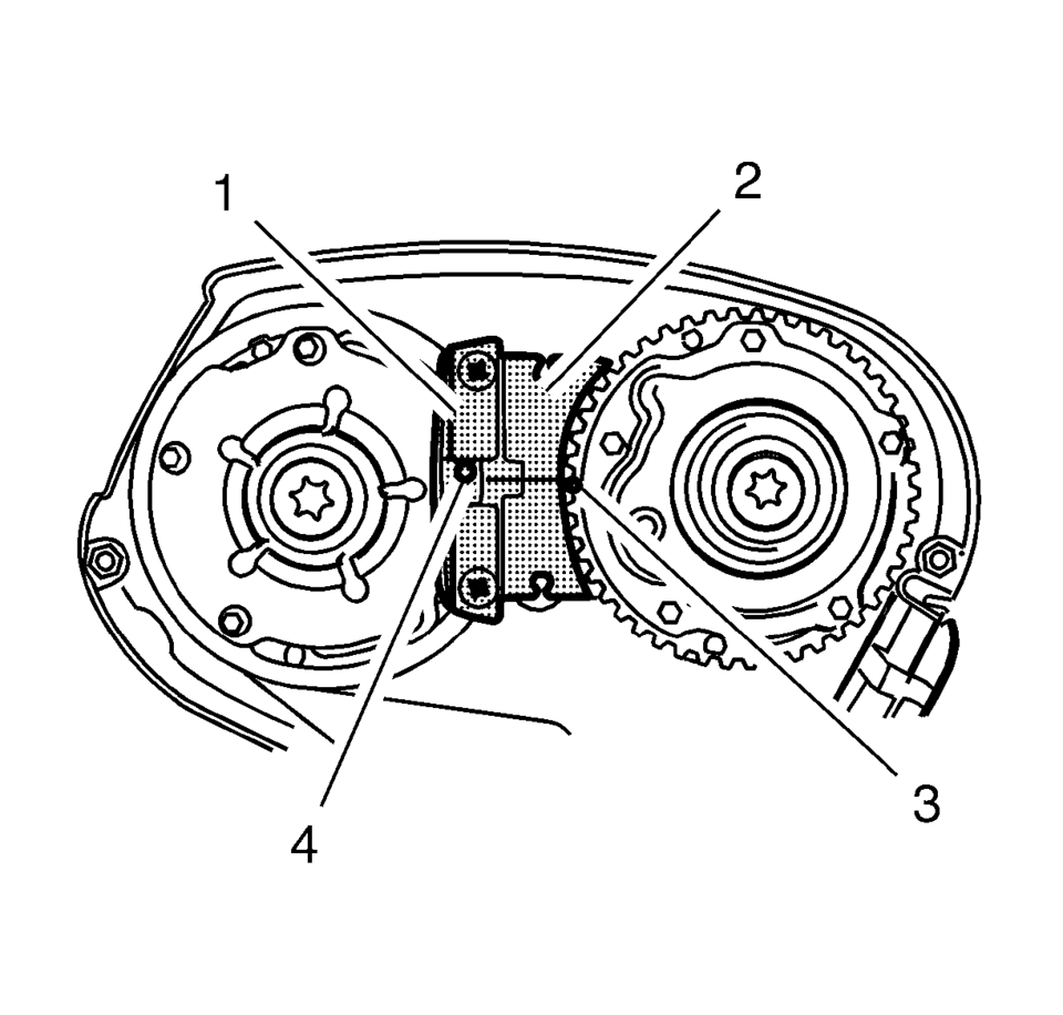
- Install the EN-6340-left locking tool (1) in the camshaft position actuator adjusters as shown.
- Install the EN-6340-right locking tool (2) in the camshaft position actuator adjusters as shown.
- Tighten the intake camshaft position actuator adjuster or exhaust camshaft
position actuator adjuster bolts to 50 Y (37 lb ft) + 150° + 15°
use the EN-45059 meter.
- Install camshaft closure bolt and tighten to 30 Y (22 lb ft)
.
- Remove the EN-6628–A locking tool.
- Clean the timing belt tensioner thread.
- Install the timing belt tensioner (2) and tighten the NEW timing belt
tensioner bolt (1) to 20 Y (15 lb ft)
.
- Install the timing belt center front cover (1) to the timing belt rear cover at 2 locations.
- Install the engine mount bracket. Refer to Engine Mount Bracket Replacement.
- Raise the vehicle.
- Install the crankshaft sprocket. Refer to Crankshaft Sprocket Installation.
- Set the crankshaft in the direction of engine rotation to TDC. Use the crankshaft balancer bolt.
- Install the timing belt idler pulley. Refer to Timing Belt Idler Pulley Installation.
- Install the timing belt. Refer to Timing Belt Replacement.
- Install the drive belt tensioner. Refer to Drive Belt Tensioner Replacement.
- Install the camshaft cover. Refer to Camshaft Cover Replacement.
- Install the air cleaner housing. Refer to Air Cleaner Assembly Replacement.
- Close the hood.
Note:
If the cover is contaminated with oil, you have to clean it close.
Note:
A second person is required. Counterhold against the hexagon of corresponding camshaft with an open-ended wrench.
Note:
The spot type marking (4) on the intake camshaft position actuator adjuster does not correspond to the groove of EN-6340-left during this process but must be somewhat above as shown.
Note:
The spot type marking (3) on the exhaust camshaft position actuator adjuster must correspond to the groove on EN-6340-right.
Caution:
Refer to Fastener Caution.
Caution:
Refer to Torque-to-Yield Fastener Caution.
Note:
A second person is required. Counterhold at the camshaft hexagon.
Note:
Install a NEW seal ring.
 Camshaft Sprocket Removal
Loosen the intake camshaft sprocket bolt (1) while holding the hexagon of
intake camshaft (2) with a wrench.
Remove the intake camshaft sprocket bolt (1) and the ...

Other materials:
Selecting the Alert Timing
The Collision Alert control is on the steering wheel. Press COLLISION ALERT to
set the alert timing to far, medium, near or off. The first button press shows the
current control setting on the DIC. Additional button presses will change this setting.
The chosen setting will remain until it is ...
Hood Hold-Open Rod Replacement
Hood Hold-Open Rod Replacement
Callout
Component Name
1
Hood Hold-Open Rod
Warning: When a hood hold open device is being removed or
installed, provide alternate support to avoid the possibility of damage
...
Steering Knuckle Replacement
Removal Procedure
Raise and support the vehicle. Refer to Lifting and Jacking the Vehicle.
Remove the tire and wheel assembly. Refer to Tire and Wheel Removal
and Installation.
Remove the wheel speed sensor from the steering knuckle. Refer to Front
Wheel Speed Sensor ...

0.0063