Chevrolet Sonic Repair Manual: Center Pillar Reinforcement Replacement
- Removal Procedure
-
- Disable the SIR system. Refer to SIR Disabling and Enabling.
- Disconnect the negative battery cable. Refer to Battery Negative Cable Disconnection and Connection.
- Remove all related panels and components.
- Visually inspect the damage. Repair as much of the damage as possible.
- Remove the sealers and anti-corrosion materials from the repair area, as necessary. Refer to Anti-Corrosion Treatment and Repair.
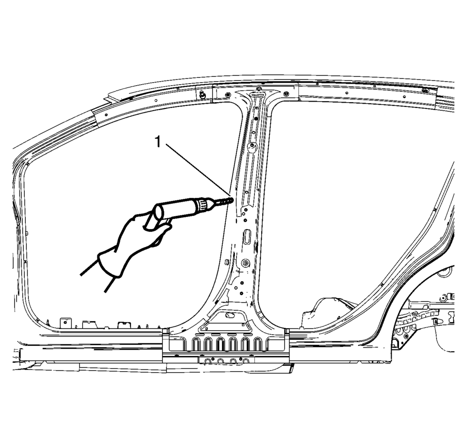
- Locate and mark all the necessary factory welds of the center pillar reinforcement.
- Drill all factory welds (1). Note the number and location of welds for installation of the service assembly.
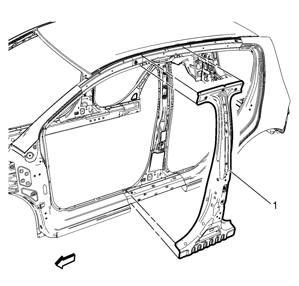
- Remove the damaged center pillar reinforcement (1).
Warning:
Refer to Approved Equipment for Collision Repair Warning.
Warning:
Refer to Glass and Sheet Metal Handling Warning.
Note:
The center pillar upper stiffener is made of Dual Phase Steel and should be replaced only at factory joints. Repairing or sectioning of this part is not recommended. Refer to Dual Phase Steel.
- Installation Procedure
-
- Prepare all mating surfaces as necessary.
- Align the center pillar reinforcement.
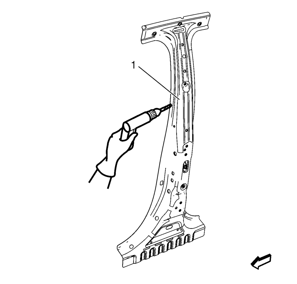
- Drill a 8?€‰mm (5/16?€‰in)
holes for plug welding along the edges of the center pillar reinforcement as noted from the original panel (1).
- Clean and prepare the attaching surfaces for welding.
- Position the center pillar reinforcement on the vehicle (1).
- Verify the fit of the center pillar reinforcement.
- Clamp the center pillar reinforcement into position.
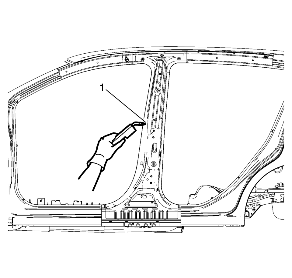
- Plug weld accordingly (1).
- Apply the sealers and anti-corrosion materials to the repair area, as necessary. Refer to Anti-Corrosion Treatment and Repair.
- Paint the repaired area. Refer to Basecoat/Clearcoat Paint Systems.
- Install all related panels and components.
- Connect the negative battery cable. Refer to Battery Negative Cable Disconnection and Connection.
- Enable the SIR system. Refer to SIR Disabling and Enabling.
 Special Tools
Illustration
Tool Number/ Description
EN-45059
J-45059
Angle Meter
...
 Drivetrain and Front Suspension Frame Skid Plate Replacement
Removal Procedure
Raise and support the vehicle. Refer to Lifting and Jacking the Vehicle.
Remove the mounting bolts?€‰(1) for the front suspension frame skid
p ...
Other materials:
Exterior Lamp Controls
The exterior lamp control is on the instrument panel to the outboard side of
the steering column.
There are four positions:
(Off): Briefly turn to this position
to turn the automatic light control off or on again.
AUTO (Automatic): Turns the headlamps on automatically at normal brightness, ...
Rear Side Door Weatherstrip Replacement - Door Side
Rear Side Door Weatherstrip Replacement - Door Side
Callout
Component Name
1
Rear Side Door Weatherstrip
Procedure
Open the front side door to the fully open position.
Remove the front side door check link bo ...
Rear Window Wiper Motor Grommet Replacement
Rear Window Wiper Motor Grommet Replacement
Callout
Component Name
Preliminary Procedure
Remove the rear window wiper motor. Refer to Rear Window Wiper Motor
Replacement.
1
Rear Window Wiper Mot ...

0.005