Chevrolet Sonic Repair Manual: Charge Air Cooler Replacement
|
Callout |
Component Name |
|---|---|
Preliminary Procedures
|
|
|
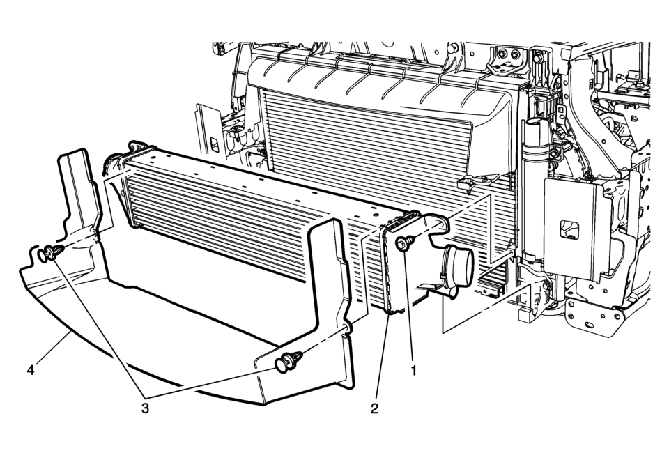
1 |
Charge Air Cooler Fastener (Qty 2) Caution: Refer to Fastener Caution.
10 Y (89 lb in) |
|
2 |
Charge Air Cooler Procedure
Pull the charge air cooler upward to release the cooler from the rubber grommets. |
|
3 |
Charge Air Cooler Air Deflector Fasteners (Qty 2) Procedure
Remove the charge air cooler air deflector fasteners. |
|
4 |
Charge Air Cooler Air Deflector |
 Charge Air Cooler Outlet Air Hose Replacement
Removal Procedure
Remove the front bumper fascia. Refer to Front Bumper Fascia Replacement.
Loosen the clamp (1) at the charge air cooler outlet pipe (2) to throt ...
 Crankshaft Position System Variation Learn
Note: The crankshaft position sensor system variation learn procedure
is required when the following service procedures have been performed, regardless
of whether DTC P0315 is set:
...
Other materials:
Front Wheelhouse Liner Inner Front Extension Replacement (Left SIde)
Front Wheelhouse Liner Inner Front Extension Replacement
Callout
Component Name
Preliminary Procedure
Remove the tire and wheel assembly. Refer to Tire and Wheel Removal and
Installation.
1
Fron ...
Air Conditioning Refrigerant Service Valve Core Replacement
Special Tools
GE-39400-A Halogen Leak Detector
GE-46246 Valve Core Removal Tool
For equivalent regional tools, refer to Special Tools.
Removal Procedure
Recover the refrigerant. Refer to Refrigerant Recovery and Recharging.
Remove the service port valve cor ...
Basic information
The front and rear sonar system in the Nissan Armada is designed to assist the
driver during parking and low-speed maneuvers by detecting obstacles around the
vehicle. Using ultrasonic sensors integrated into the front and rear bumpers, the
Nissan Armada provides audible tones and visual i ...

0.0075