Chevrolet Sonic Repair Manual: Control Solenoid Valve and Transmission Control Module Assembly Inspection
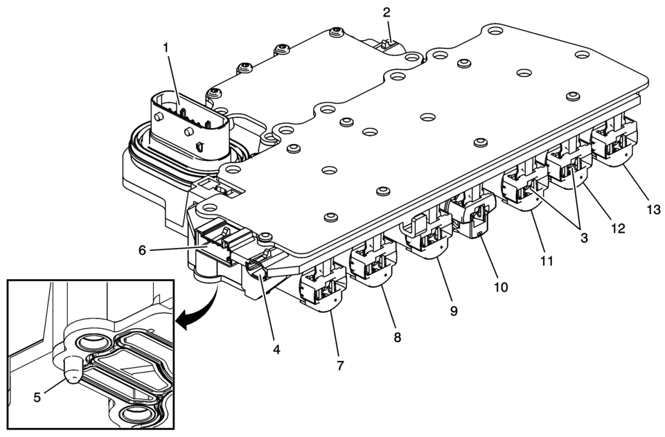
- Verify the conditions listed below do not exist. Carefully inspect the control solenoid valve assembly connectors and pins (1, 2, 4, 6) for the condition. Repair or replace as necessary.
- Damage
- Bent pins
- Debris
- Broken retaining tab
- Contamination
|
Solenoid Name |
Illustration Number |
Expected Resistance Ω |
|---|---|---|
|
Pressure Control Solenoid 3 |
7 |
3.42?.18 |
|
Pressure Control Solenoid 2 |
8 |
3.42?.18 |
|
TCC Pressure Control Solenoid Valve |
9 |
3.42?.18 |
|
Shift Solenoid Valve 1 |
10 |
16.2?9.8 |
|
Pressure Control Solenoid 5 |
11 |
3.42?.18 |
|
Pressure Control Solenoid 4 |
12 |
3.42?.18 |
|
Line Pressure Control Solenoid Valve |
13 |
3.42?.18 |
 Automatic Transmission Range Selector Lever Replacement
Removal Procedure
Set the park brake and chock the wheels.
Disconnect the transmission range selector lever cable
terminal (1) from the transmission manual shift leve ...
 Control Solenoid Valve and Transmission Control Module Assembly Installation
Control Solenoid Valve and Transmission Control Module Assembly Installation
Callout
Component Name
1
Control Solenoid V ...
Other materials:
OnStar Description and Operation
This OnStar® system consists of the following components:
Telematics communication interface control module
OnStar® three button assembly
Microphone
Cellular antenna
Navigation antenna
Bluetooth® antenna (If equipped)
Back up battery (If equipped)
This system also interfaces wi ...
Bluetooth (Overview)
For vehicles equipped with Bluetooth capability, the system can interact with
many cell phones, allowing:
Placement and receipt of calls in a hands-free mode.
Sharing of the cell phone’s address book or contact list with the vehicle.
To minimize driver distraction, before driving, and ...
Radiator Inlet Hose Replacement (LUV)
Radiator Inlet Hose Replacement
Callout
Component Name
Preliminary Procedures
Drain the engine coolant. Refer to Cooling System Draining and Filling.
Remove the fasteners securing the radiator surge tank to the vehicle
...

0.0054