Chevrolet Sonic Repair Manual: Control Valve Body Assembly Removal
| Table 1: | Control Valve Body Cover Removal |
| Table 2: | Control Solenoid (With Body and TCM) Valve Assembly Removal |
| Table 3: | Control Valve Body Assembly Removal |
- Control Valve Body Cover Removal
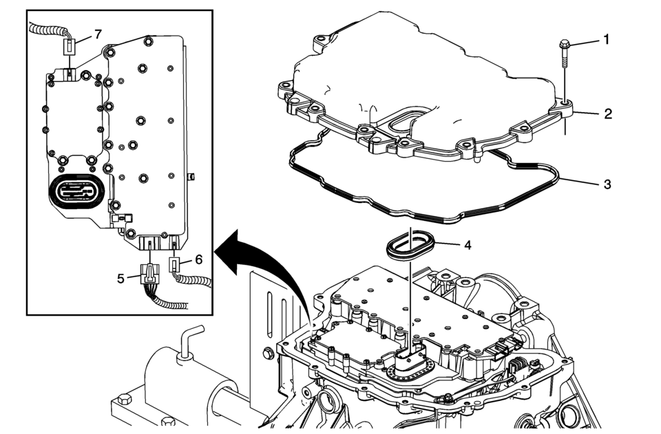
Control Valve Body Cover Removal Callout
Component Name
1
Control Valve Body Cover Bolts M6 x 30 (Qty: 13)
2
Control Valve Body Cover
3
Control Valve Body Gasket
Note:
Discard the seal. It is not reusable.
4
Control Valve Body Cover Wiring Connector Hole Seal
Caution:
Support the control solenoid valve assembly around the connector when removing the seal. Excessive pulling force can damage the internal electrical connections.
Note:
Discard the seal. It is not reusable.
5
Shift Position Switch Connector
6
Output Speed Sensor Connector
7
Input Speed Sensor Connector
- Control Solenoid (With Body and TCM) Valve Assembly Removal
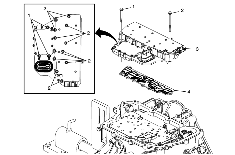
Control Solenoid (With Body and TCM) Valve Assembly Removal Callout
Component Name
1
Control Valve Body M5 x 40.5 (Qty: 3)
2
Control Valve Body Bolt M6 x 30 (Qty: 12)
3
Control Solenoid (with Body and TCM) Valve Assembly
4
Control Solenoid Valve Assembly Filter Plate
Caution:
Use care when removing or installing the filter plate assembly. A broken or missing retaining tab may not adequately secure the filter plate to the control solenoid valve assembly, resulting in possible damage or contamination.
Note:
Discard the filter plate. It is not reusable.
- Control Valve Body Assembly Removal
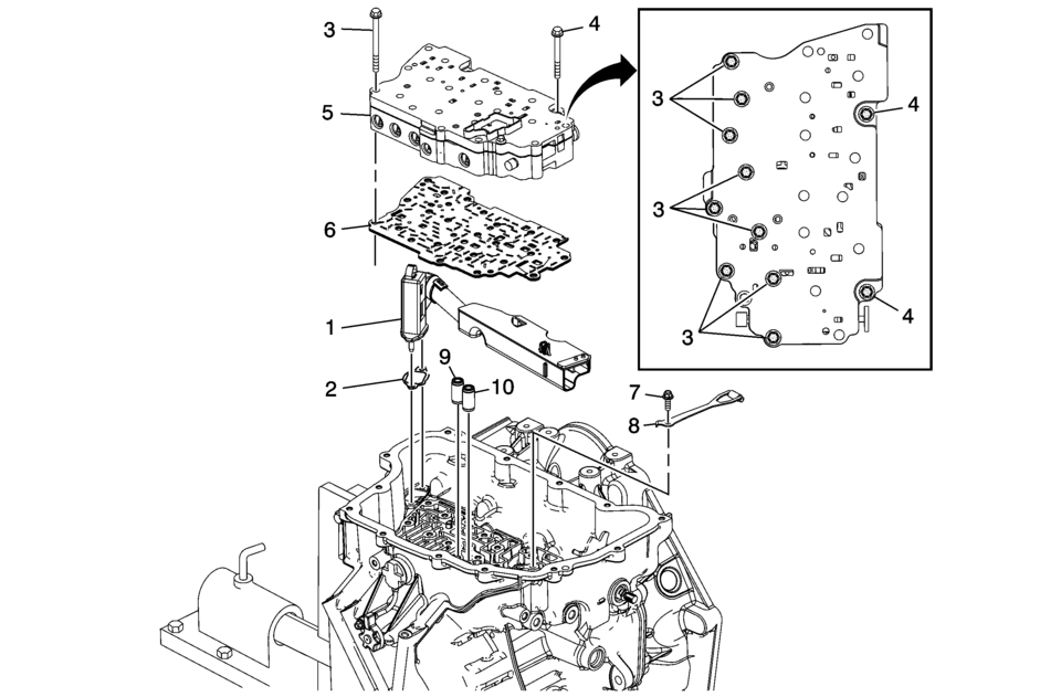
Control Valve Body Assembly Removal Callout
Component Name
1
Fluid Level Control Valve
2
Fluid Level Control Valve Gasket
3
Control Valve Body Bolt M6 x 60 (Qty: 9)
4
Control Valve Body Bolt M6 x 53 (Qty: 2)
5
Control Valve Body Assembly
6
Control Valve Body Spacer Plate Assembly
7
Manual Shaft Detent Spring Bolt M6 x 16 (Qty: 1)
8
Manual Shaft Detent Lever Spring Assembly
9
1-2-3-4 Clutch Fluid Passage Seal
Note:
Discard the seal. It is not reusable.
10
Low/Reverse Clutch Fluid Passage Seal
Note:
Discard the seal. It is not reusable.
 Control Valve Body Assembly Installation
Control Valve Body Assembly Installation
Callout
Component Name
1
Low and Reverse Clutch Fluid Passage Seal
...
 Control Valve Body Cleaning and Inspection (Gen 2)
Control Valve Body Cleaning and Inspection
Callout
Component Name
Warning: Valve springs can be tightly compressed. Use care
...
Other materials:
Passenger Sensing System
The vehicle has a passenger sensing system for the front outboard passenger position.
The passenger airbag status indicator will light on the instrument panel when the
vehicle is started.
United States
Canada
The words ON and OFF, or the symbol for on and off, will be visible during the
...
Radio with Touchscreen
The infotainment system can play music or movies by connecting an auxiliary device
to the USB port, if equipped.
USB Support
USB Supported Devices
USB Flash Drives
Portable USB Hard Drives
2G-5G iPod nano®
1G-3G iPod touch®
120GB/160GB iPod classic®
3G/3GS/4/4S iPhone®
Not a ...
Air Conditioning Compressor Replacement (LUV)
Air Conditioning Compressor Replacement
Callout
Component Name
Preliminary Procedure
Recover the refrigerant. Refer to Refrigerant Recovery and Recharging.
Raise and support the vehicle. Refer to Lifting and Jacking the
...

0.007