Chevrolet Sonic Repair Manual: Control Valve Body Cover Installation
|
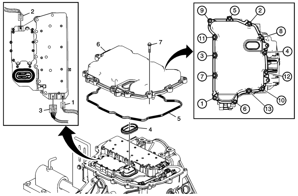
Callout |
Component Name |
|---|---|
|
1 |
Input Speed Sensor Connector |
|
2 |
Output Speed Sensor Connector |
|
3 |
Shift Position Switch Connector |
|
4 |
Control Valve Body Cover Wiring Connector Hole Seal Note: Do not re-use the valve body cover wiring connector hole seal. |
|
5 |
Control Valve Body Cover Gasket Note: Do not re-use the valve body cover gasket. |
|
6 |
Control Valve Body Cover |
|
7 |
Control Valve Body Cover Bolts M6 x 30 (Qty: 13) Caution: Refer to Fastener Caution.
12 Y (106 lb in) |
 Control Valve Body Cleaning and Inspection (Gen 2)
Control Valve Body Cleaning and Inspection
Callout
Component Name
Warning: Valve springs can be tightly compressed. Use care
...
 Control Valve Body Cover Replacement
Removal Procedure
Disconnect the battery negative cable. Refer to
Battery Negative Cable Disconnection and Connection.
Raise and support the vehicle. Refer to
Lifting and Jac ...
Other materials:
Steering Wheel Airbag Coil Replacement
Steering Wheel Airbag Coil Replacement
Callout
Component Name
Preliminary Procedures
Remove the steering wheel. Refer to Steering Wheel Replacement.
Remove the steering column upper trim cover. Refer to Steering Column
...
Rear Brake Cylinder Replacement
Removal Procedure
Warning: Refer to Brake Dust Warning.
Warning: Refer to Brake Fluid Irritant Warning.
Raise and support the vehicle. Refer to Lifting and Jacking the Vehicle.
Remove the tire and wheel assembly. Refer to Tire and Wheel Removal
and I ...
Basic information
WARNING
Never operate your Nissan Armada while the parking brake is engaged.
Driving with the parking brake applied can cause overheating, reduced braking
performance, and eventual brake failure, significantly increasing the risk of
an accident.
Do not release the parking brake of you ...

0.0069