Chevrolet Sonic Repair Manual: Control Valve Channel Plate Cleaning and Inspection (6T30/40/45/50 - Gen 2)
|
Callout |
Component Name |
|---|---|
|
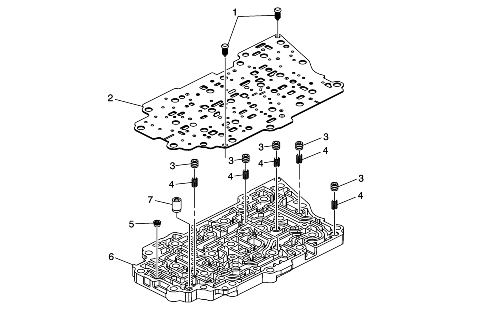
1 |
Control Valve Body Spacer Plate Retainer |
|
2 |
Channel Plate to Valve Body Spacer Plate Assembly |
|
3 |
Actuator Feed Accumulator Piston (Qty: 5) |
|
4 |
Actuator Feed Accumulator Spring (Qty: 5) |
|
5 |
Variable Hi and 2-3-4 Clutch Housing Valve Ball |
|
6 |
Valve Channel Plate Note: Inspect the channel plate bolt pass through holes for damage or brinelling. Any damage will cause incorrect pressure switch operation. Replace as necessary. |
|
7 |
Control Valve Channel Plate Ball Spring Assembly |

 Definitions and Abbreviations
Throttle Positions
Engine Braking
A condition where the engine is used to slow the vehicle by manually
downshifting during a zero throttle coastdown.
Full Throttle Down ...
Other materials:
Remote Control Door Lock, Theft Deterrent, and Remote Start Transmitter Package
Installation
Installation Instructions Part Number
22880351
20997377
95198137
22901614
92233547
Kit Usage
This kit adds remote start to vehicles without option BTV. The vehicle
must also have an automatic transmission. Both can be verified by using the
GM Vehicle Inquiry System (GMVIS) ...
Intake Manifold Removal
Note: Intake manifold bolts remain in intake manifold screw bores.
Remove the 6 intake manifold bolts (1).
Remove the intake manifold (1) along with the intake manifold gasket.
...
The C300 competes well on fuel economy
Title: "2023 Mercedes-Benz C300: A Detailed Look at Efficiency, Interior, and Customization Options"
The 2023 Mercedes-Benz C300 presents a compelling choice for luxury sedan enthusiasts, offering a blend of performance, efficiency, and customizable features. Here's a breakdown of wh ...

0.0051