Chevrolet Sonic Repair Manual: Crankshaft and Bearing Installation
Special Tools
EN-45059 Torque Angle Sensor Kit
For equivalent regional tools, refer to Special Tools
- Install the crankshaft bearing clips, oil bearing clips.
- Install the crankshaft.
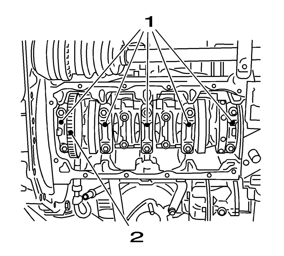
- Install the crankshaft bearing caps 1-4.
Note:
Inspect the installation position.
Note:
Inspect the installation position.
- Oil bearing clips.
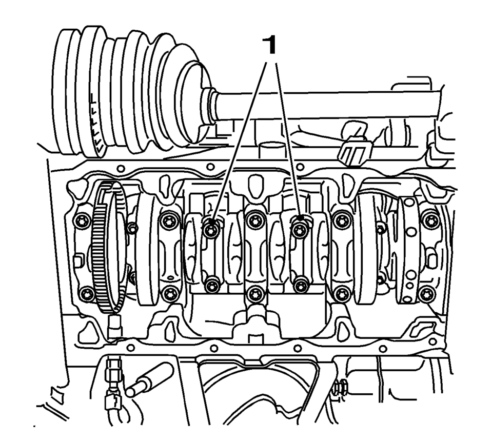
- Install the 8 NEW crankshaft bearing cap bolts.
Note:
Inspect the installation position.
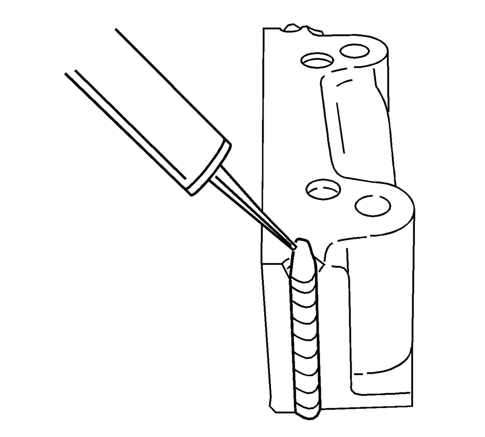
- Apply black adhesive sealing compound to the grooves of the rear crankshaft bearing cap.
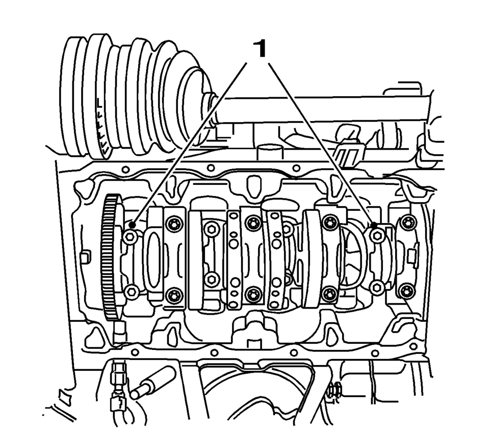
- Install the 2 NEW crankshaft bearing cap bolts.
Caution:
Refer to Fastener Caution.
Caution:
Refer to Torque-to-Yield Fastener Caution.
- First pass to 50 Y (37 lb ft)
- Second pass to 45°
- Third pass to 15°
Note:
Inspect the installation position.
- First pass to 35 Y (26 lb ft)
- Second pass to 45°
- Third pass to 15°
.
Note:
Inspect the installation position.
- First pass to 35 Y (26 lb ft)
- Second pass to 45°
- Third pass to 15°
 Crankshaft and Bearing Cleaning and Inspection
Special Tools
EN-45059 Torque Angle Sensor Kit
GE-571-B Dial Gauge
For equivalent regional tools, refer to Special Tools.
Crankshaft End Play, Check
Note: Cranksha ...
 Crankshaft and Bearing Removal
Identify all the connecting rod bearing caps (1).
Remove the 4 bolts.
Remove the connecting rod bearing caps 1 and 4 (1).
Turn the crankshaft through 180 ...
Other materials:
Instrument Panel, Leather, Vinyl, Other Plastic Surfaces, Low Gloss Paint Surfaces
and Natural Open Pore Wood Surfaces
Use a soft microfiber cloth dampened with water to remove dust and loose dirt.
For a more thorough cleaning, use a soft microfiber cloth dampened with a mild soap
solution.
Caution
Soaking or saturating leather, especially perforated leather, as well as other
interior surfaces, may cause per ...
Drivetrain and Front Suspension Frame Skid Plate Replacement
Removal Procedure
Raise and support the vehicle. Refer to Lifting and Jacking the Vehicle.
Remove the mounting bolts?€‰(1) for the front suspension frame skid
plate.
Remove the front suspension frame skid plate?€‰(2).
Installation Procedur ...
Transmission Assemble (Gen 2)
Special Tools
3-9506289 Universal Adapter
R-0007758 Holding Fixture
S-9407197 Differential Rotating Tool
S-9407198 Differential Bearing Race Wrench
For equivalent regional tools, refer to Special Tools.
Install the clutch and differential housing assembly (1)
onto ...

0.0054