Chevrolet Sonic Repair Manual: Cylinder Head Assemble
Special Tools
- EN-958 Valve Stem Seal Installer
- EN-8062 Valve Spring Compressor
- EN-8062-5 Adapter
- EN-50717-2 Compressor Assembly of EN-50717 Kit
For equivalent regional tools, refer to Special Tools.
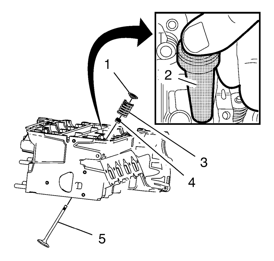
- Lubricate the valve stem and the valve guide with clean engine oil.
- Install the valve (5).
- Install the NEW valve stem oil seal (4), using the EN-958 installer (2).
- Loosely install the valve spring (3) and the valve spring retainer (1).
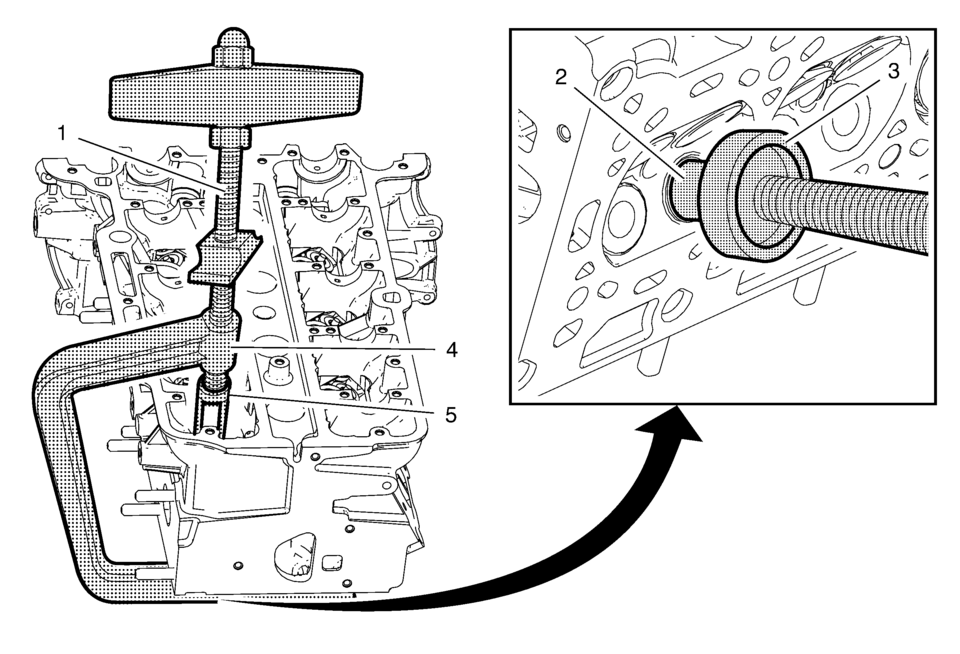
- Install the EN-50717?E assembly (1) to the EN-8062 compressor (4).
- Install the EN-8062?E adapter (3) to the EN-8062 compressor .
- Install the compressor assembly to the cylinder head, so that the adapter (5) of the EN-50717?E assembly (1) contacts the valve spring retainer properly and the EN-8062?E adapter (3) contacts the valve disc (2). Prefix the EN-8062 compressor (4).
- Apply pressure to the EN-50717?E assembly to push down the vale spring retainer (1) and compress the valve spring (3) until the valve keys (2) can be inserted. Carefully insert the valve keys then, so that they are proper installed to the valve stem grooves.
- Carefully release the tension from the EN-50717?E assembly .
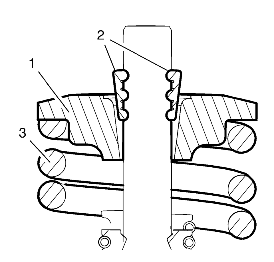
- Inspect the valve keys and valve spring retainers for proper seat.
- Remove the compressor assembly from the cylinder head.
- Repeat the procedure with the remaining valves.
Note:
Ensure all valve train components will be installed in their original position.
Caution:
The valve stem keys must correctly seat in the valve spring cap. Engine damage may occur by not installing properly.
 Cylinder Head
...
 Cylinder Head Cleaning and Inspection
Valve Cleaning and Inspection
Warning: Bodily injury may occur if the cleaning solvent is
inhaled or exposed to the skin.
Note: Do not scratch the valve ste ...
Other materials:
Wheel Drive Shafts Description and Operation
Front wheel drive axles are flexible assemblies.
Front wheel drive axles consist of the following components:
A front wheel drive shaft tripot joint (inner joint)
A front wheel drive shaft constant velocity joint (outer joint)
A front wheel drive shaft
The front wheel drive shaft connec ...
Heater Core Outlet Tube Replacement
Heater Core Outlet Tube Replacement
Callout
Component Name
Preliminary Procedures
Remove the Heater and Air Conditioning Evaporator and Blower Module.
Refer to Heater and Air Conditioning Evaporator and Blower Module Removal
...
Use of Room Temperature Vulcanizing (RTV) and Anaerobic Sealant
Pipe Joint Compound
Note: Three types of sealer are commonly used in engines. These
are RTV sealer, anaerobic gasket eliminator sealer, and pipe joint compound.
The correct sealer and amount must be used in the proper location to prevent
oil leaks. DO NOT interchange the 3&# ...

0.0066