Chevrolet Sonic Repair Manual: Differential Case Assemble
Special Tools
- J-810721 Axle Shaft Seal Remover Support Base
- R-0407011 Bearing Race Remover
- R-0407012 Differential Carrier Cone Bearing Cap Driver
- R-0007761 Universal Handle for Pullers and Installers
- S-9407194 Speed Sensor Impeller Ring Installer
- S-9407195 Pinion Gear Case Bearing Installer
- S-9707500 Seal Installer
For equivalent regional tools, refer to Special Tools.
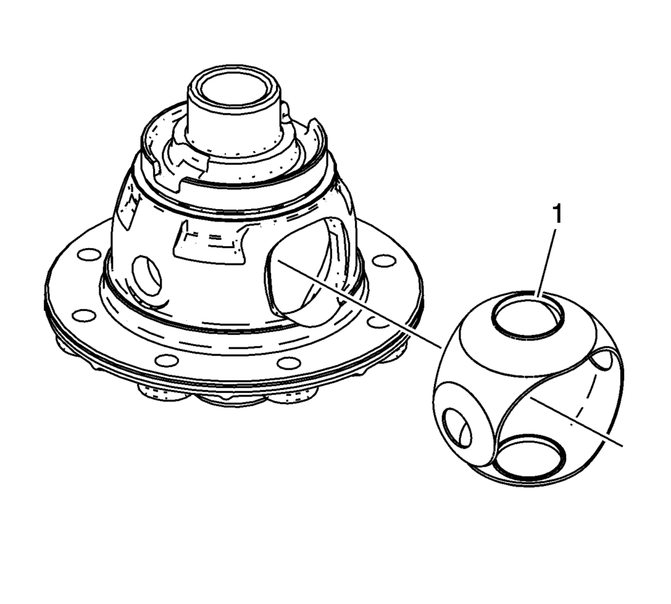
- Install the front differential pinion and side gear thrust washer. It must be possible to insert the collar (1) of the thrust washer into the guide for the pinion gears in the housing.
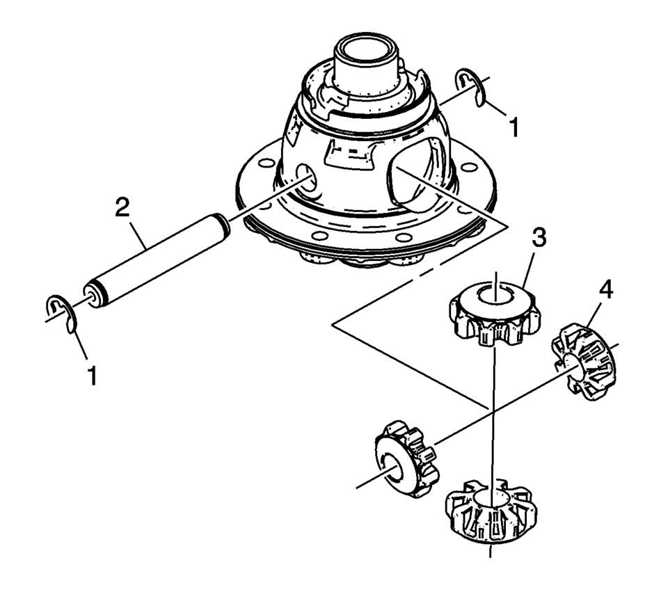
- Install the front differential pinion gears (3) and side gears (4).
- Install the front differential pinion gear shaft (2) and the pinion gear shaft retaining washers (1).
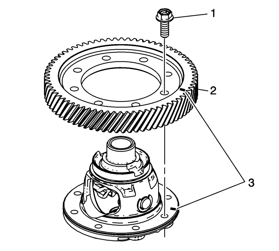
- If both components are reused align the assembly marks (3).
- Install the front differential ring gear (2).
- Install the front differential ring gear bolts (1). Tighten to 90 N•m
(66.4 lb ft)
.
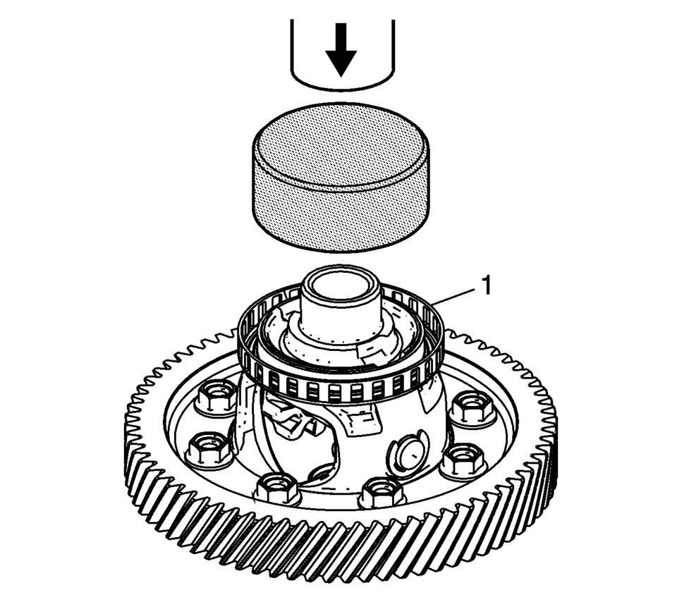
- Install the ring front wheel speed sensor reluctor wheel (1) using the S-9407194 installer and a hydraulic press.
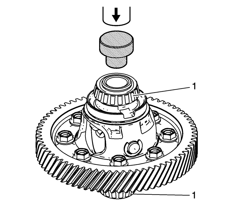
- Install the front differential bearing assemblies (1) using the S-9407195 installer and a hydraulic press.
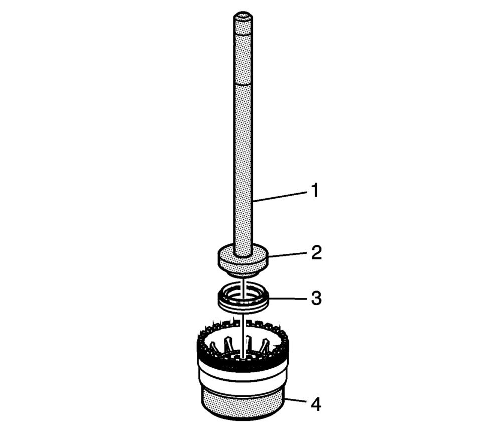
- Install the front wheel drive shaft oil seal (3) using the R-0007761 handle (1), S-9707500 seal installer (2), and the J-810721 support base (4).
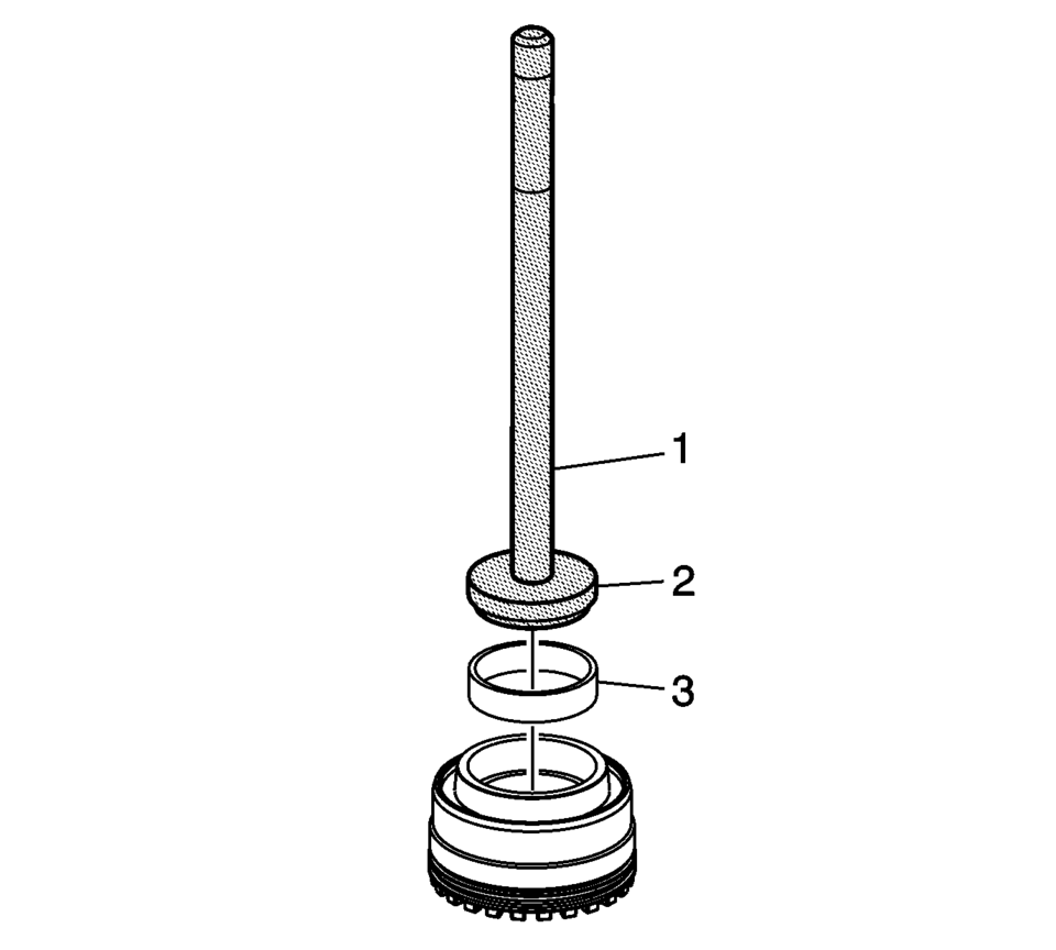
- Install the front differential bearing race (3) using the R-0007761 handle (1) and the R-0407012 driver (2).
Note:
Lubricate rotating parts on their bearing, running, seating, and pressure surfaces using transmission fluid.
Warning:
Refer to Safety Glasses Warning.
 Differentials
...
 Differential Case Disassemble
Special Tools
6-9607346 Sensor Ring Gear Puller
J-810704 Steering Column Center Bar Puller
J-810721 Axle Shaft Seal Remover Support Base
R-0006749 Support Base
R-0407011 Bearing Race Rem ...
Other materials:
Rear Bumper Impact Bar Replacement (Sedan)
Rear Bumper Impact Bar Replacement
Callout
Component Name
Preliminary Procedure
Remove the rear bumper fascia. Refer to Rear Bumper Fascia Replacement.
1
Rear Bumper Impact Bar Bolt (Qty:?€‰4 ...
Air Conditioning Compressor and Condenser Hose Replacement (LUV)
Removal Procedure
Recover the refrigerant. Refer to Refrigerant Recovery and Recharging.
Remove the drivetrain and front suspension frame skid plate if equipped.
Refer to Drivetrain and Front Suspension Frame Skid Plate Replacement.
Remove the front fascia assembly. Re ...
Turbocharger Oil Feed Pipe Replacement
Removal Procedure
Open the hood.
Disconnect battery negative cable. Refer to Battery Negative Cable Disconnection
and Connection.
Remove the exhaust manifold heat shield. Refer to Exhaust Manifold Heat
Shield Replacement.
Remove the turbocharger oil feed p ...

0.0059