
Chevrolet Sonic Repair Manual: Differential Case Assemble
Special Tools
- J-810721 Axle Shaft Seal Remover Support Base
- R-0407011 Bearing Race Remover
- R-0407012 Differential Carrier Cone Bearing Cap Driver
- R-0007761 Universal Handle for Pullers and Installers
- S-9407194 Speed Sensor Impeller Ring Installer
- S-9407195 Pinion Gear Case Bearing Installer
- S-9707500 Seal Installer
For equivalent regional tools, refer to Special Tools.
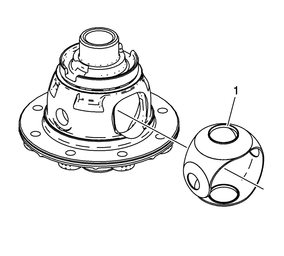
- Install the front differential pinion and side gear thrust washer. It must be possible to insert the collar (1) of the thrust washer into the guide for the pinion gears in the housing.
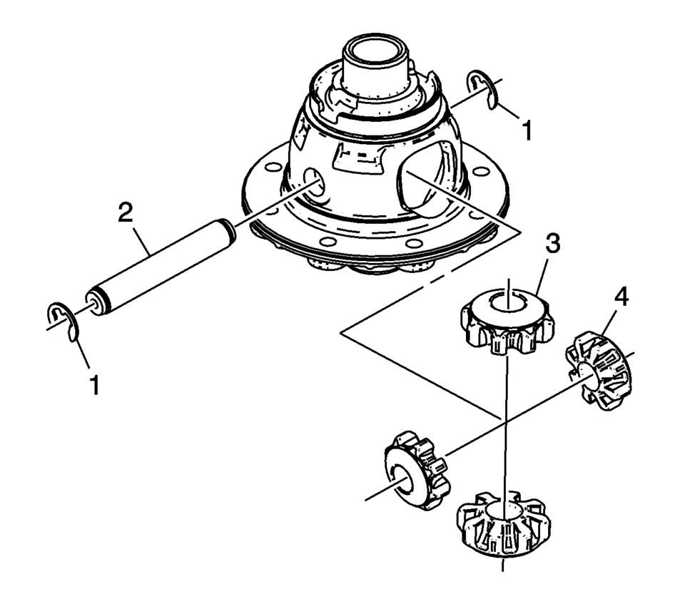
- Install the front differential pinion gears (3) and side gears (4).
- Install the front differential pinion gear shaft (2) and the pinion gear shaft retaining washers (1).
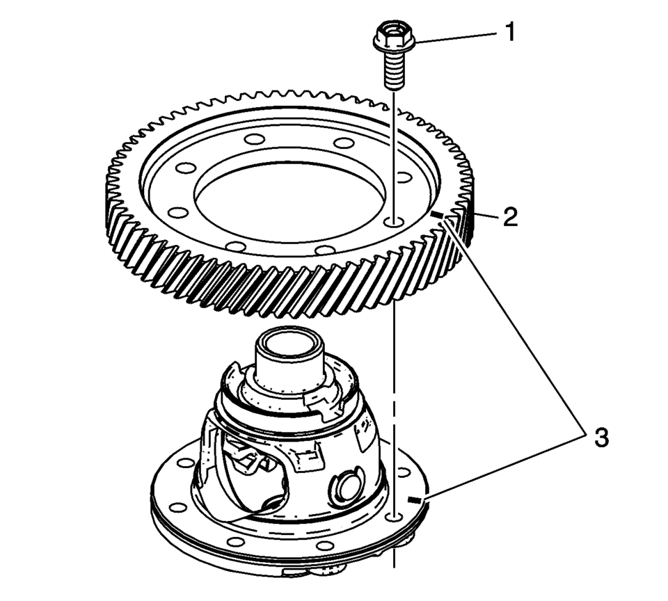
- If both components are reused align the assembly marks (3).
- Install the front differential ring gear (2).
- Install the front differential ring gear bolts (1). Tighten
to 90 N? (66.4 lb ft)
.
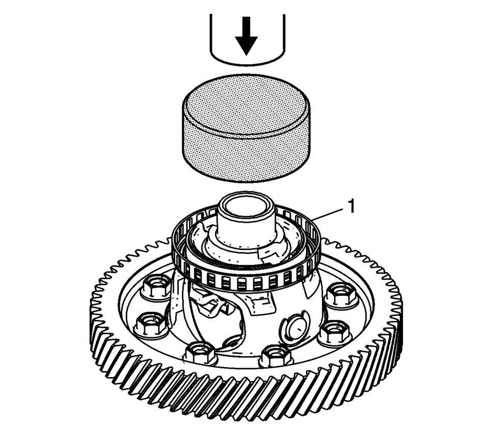
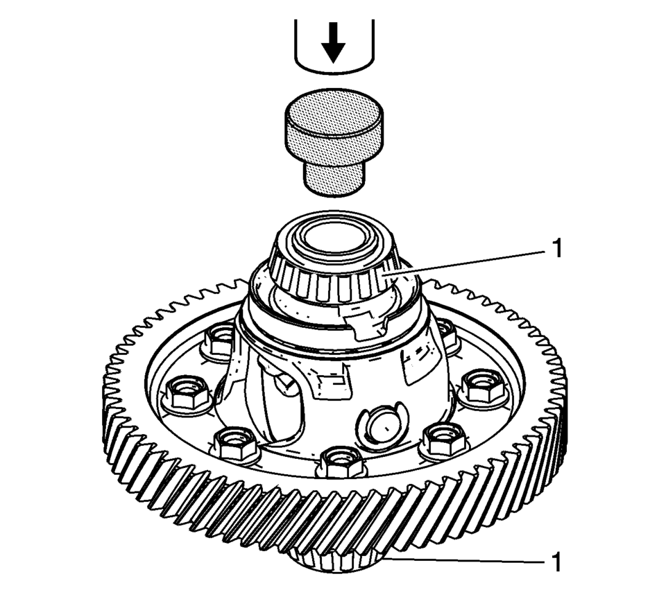
- Install the ring front wheel speed sensor reluctor wheel (1) using the S-9407194 installer and a hydraulic press.
- Install the front differential bearing assemblies (1) using the S-9407195 installer and a hydraulic press.
- Install the front wheel drive shaft oil seal (3) using the R-0007761 handle (1), S-9707500 seal installer (2), and the J-810721 support base (4).
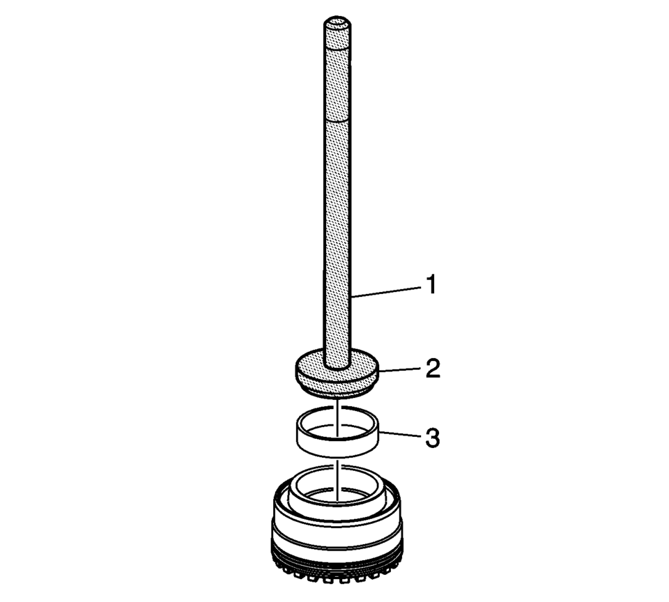
- Install the front differential bearing race (3) using the R-0007761 handle (1) and the R-0407012 driver (2).
Note:
Lubricate rotating parts on their bearing, running, seating, and pressure surfaces using transmission fluid.
Warning:
Refer to Safety Glasses Warning.

 Clutch and Differential Housing Disassemble
Special Tools
M-680770 Universal Sliding Mallet
R-0007758 Holding Fixture
R-0407008 Counter Shaft Bearing Remover
R-0407010 Input Shaft Needle Bearing Puller and Driver
R-0407013 Gearshi ...
 Differential Case Disassemble
Special Tools
6-9607346 Sensor Ring Gear Puller
J-810704 Steering Column Center Bar Puller
J-810721 Axle Shaft Seal Remover Support Base
R-0006749 Support Base
R-0407011 Bearing Race Rem ...
Other materials:
Outside Rearview Mirror Remote Control Switch Replacement
Outside Rearview Mirror Remote Control Switch Replacement
Callout
Component Name
Preliminary Procedure
Remove the front side door widow switch bezel. Refer to Front Side Door
Window Switch Bezel Replacement.
...
Replacing LATCH System Parts After a Crash
Warning: A crash can damage the LATCH system in the vehicle. A damaged
LATCH system may not properly secure the child restraint, resulting in serious
injury or even death in a crash. To help make sure the LATCH system is working
properly after a crash, see your dealer to have the system ...
Inspection/Maintenance Complete System Set Procedure
Diagnostic Instructions
Perform the Diagnostic System Check - Vehicle
prior to using this diagnostic procedure.
Review Strategy Based Diagnosis for an
overview of the diagnostic approach.
Diagnostic Procedure Instructions provides
an overview of each diagnostic cat ...

0.0116