Chevrolet Sonic Repair Manual: Drive Range, Second Gear (Gen 2)
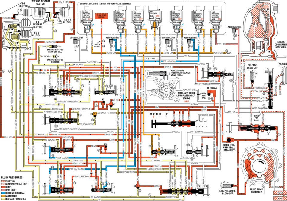
As vehicle speed increases and operating conditions become appropriate, the transmission control module (TCM) processes input signals from the automatic transmission input and output speed sensors, the throttle position sensor and other vehicle sensors to determine the precise moment to command ON the normally-low 26 pressure control solenoid and shift the transmission into Second gear. The manual valve remains in the Drive (D) position and line pressure continues to feed the drive fluid circuit.
- 2-6 Clutch Applies
-
26 Pressure Control (PC) Solenoid
The 26 PC solenoid is commanded ON, allowing actuator feed limit fluid to enter the PCS 26 clutch fluid circuit. PCS 26 clutch fluid is then routed through orifice #24 to the 2-6 clutch regulator valve.
2-6 Clutch Regulator Valve
PCS 26 clutch fluid, at the 2-6 clutch regulator valve, opposes 2-6 clutch regulator valve spring force and orificed 26 clutch fluid pressure to regulate drive fluid pressure into the 26 clutch circuit. 26 clutch fluid is then routed through orifice #22 to the 2-6 clutch assembly in the transmission case, and through orifice #4 to the spring end of the 2-6 clutch regulator valve.
2-6 Clutch
The 26 clutch fluid from the 2-6 clutch regulator valve is routed through the transmission case to the 2-6 clutch piston assembly. The 26 clutch fluid pressure moves the piston against 2-6 clutch spring force to apply the 2-6 clutch plates.
Accumulator
PCS 26 clutch fluid is also routed to an accumulator valve. The accumulator valve is used to dampen any pressure irregularities occurring in the PCS 26 clutch fluid circuit. This helps to control clutch apply fluid pressure and clutch apply feel.
- Drive Range, Second Gear ?#8201;Gen 2/Hybrid
solenijid valve assembly ms pres pre press pressure n.h. off off off clutch accnmuumn clutch tdrdue converter assemnlv exhaust ex ex backhll release cddleh at blow-off ex valve mc release auxiliary fluid pumpassembly (bas+) clutch feedback off ex ii sucnuu h_ sun ree ..... 35 rev clutch pcs reverse default sulenoid :ex -drive drive 25 fluid mu ehedkball feed pcszg clutch ex reverse fluid pnessunes sucnou lube lime line pressure solenoid signal 1_ clutch clutch :i exhaust backfill ,, ,,
 Drive Range, Second Gear (Gen 1)
As vehicle speed increases and operating conditions become appropriate, the transmission
control module (TCM) processes input signals from the automatic transmission input
and output speed sensors ...
 Drive Range, Sixth Gear (Gen 1)
As vehicle speed increases, the transmission control module (TCM) processes input
signals from the automatic transmission input and output speed sensors, the throttle
position sensor and other veh ...
Other materials:
Speaker Replacement Reference
Speaker Replacement Reference
Component
Repair Instruction
Front Door Speaker
Radio Front Side Door Speaker Replacement
Front Tweeter Speaker
Radio Windshield Side Garnish Molding Speaker
...
Radio Front Side Door Speaker Replacement
Radio Front Side Door Speaker Replacement
Callout
Component Name
Preliminary Procedure
Remove the front side door trim. Refer to Front Side Door Trim Replacement.
1
Radio Front Side Door Speaker ...
Control Valve Body Assembly Disassemble (Gen 1)
Control Valve Body Assembly Disassemble
Callout
Component Name
1
Control Solenoid Valve Support
2
Control Valve Body Bolt M5 x 40.5 (Qty: 1)
3
...

0.0063