Chevrolet Sonic Repair Manual: Drum Brake Adjustment
Special Tools
CH-21177-A Drum to Brake Shoe Clearance Gauge
For equivalent regional tools, refer to Special Tools.
- Ensure the park brake lever is in the fully released position.
- Remove the front floor console cupholder insert.
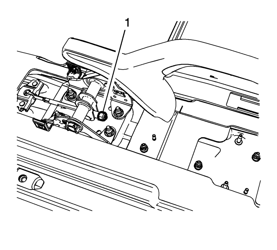
- Using ONLY HAND TOOLS, loosen the adjusting nut (1) completely to the end of the front cable threaded rod.
- Raise and support the vehicle. Refer to Lifting and Jacking the Vehicle.
- Remove the rear tire and wheel assemblies. Refer to Tire and Wheel Removal and Installation.
- Remove the brake drums. Refer to Brake Drum Replacement.
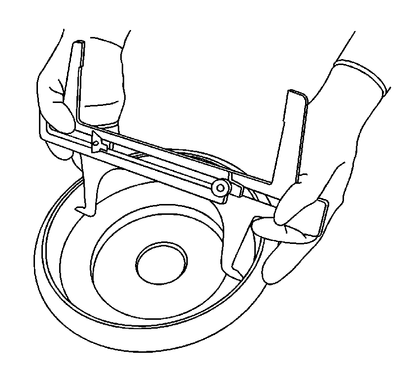
- Position the CH-21177-A Drum to Brake Shoe Clearance Gauge to the widest point of the brake drum inside diameter.
- Firmly hand tighten the set screw on the CH-21177-A Drum to Brake Shoe Clearance Gauge .
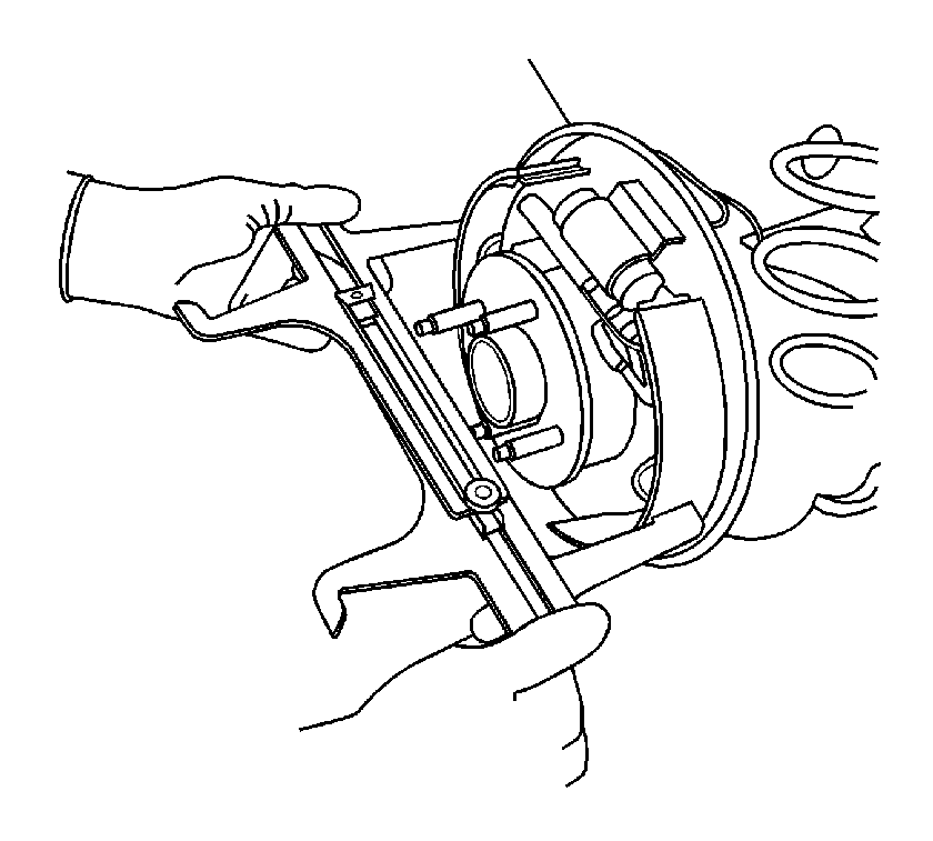
- Remove the CH-21177-A Drum to Brake Shoe Clearance Gauge from the brake drum and position it over the corresponding brake shoe assembly at its widest point.
- While holding the CH-21177-A Drum to Brake Shoe Clearance Gauge in position, insert a proper feeler gauge between one side of the CH-21177-A Drum to Brake Shoe Clearance Gauge , and the corresponding brake shoe lining.
- Rotate the brake shoe adjuster screw until the brake shoe linings contact the CH-21177-A Drum to Brake Shoe Clearance Gauge and the feeler gauge. Refer to Drum Brake Component Specifications.
- Repeat the above steps for the opposite brake drum and brake shoe assembly.
- Install the brake drums. Refer to Brake Drum Replacement.
- Adjust the park brake. Refer to Parking Brake Adjustment.
- Install the rear tire and wheel assemblies. Refer to Tire and Wheel Removal and Installation.
- Lower the vehicle.
- Install the front floor console cupholder insert.
Warning:
Refer to Brake Dust Warning.
Note:
Use ONLY HAND TOOLS when loosening or tightening the adjusting nut.
 Drum Brake Adjusting Hardware Replacement (J93, J94)
Removal Procedure
Warning: Refer to Brake Dust Warning.
Raise and support the vehicle. Refer to Lifting and Jacking the Vehicle.
Remove the tire and wheel assembly. Re ...
 Drum Brake Hardware Inspection
Warning: Refer to Brake Dust Warning.
Visually inspect the drum brake upper return spring (1) for the following
conditions:
Excessive corrosion
Excessive stretchin ...
Other materials:
Door Lock and Ignition Lock Folding Key Blade Removal and Installation
Special Tools
BO-51098 Flip Key Blade Fixture
For equivalent region tools, refer to Special Tools.
Caution: Failure to properly support the Remote Keyless Entry
(RKE) transmitter assembly while replacing the key blade may cause internal
damage to the transmitter assembly. ...
Tire Pressure Monitor Description and Operation
Tire Pressure Monitoring Block Diagram
...
Manual Shift Shaft Seal Installation
Manual Shift Shaft Seal Installation
Callout
Component Name
1
Manual Shift Shaft Seal
Special Tool
DT-49101 Seal Installer
For equivalent regional tools, refer to Special
Tools.
...

0.0062