Chevrolet Sonic Repair Manual: Drum Brake Hardware Replacement (J93, J94)
- Removal Procedure
-
- Raise and support the vehicle. Refer to Lifting and Jacking the Vehicle.
- Remove the tire and wheel assembly. Refer to Tire and Wheel Removal and Installation.
- Remove the brake drum. Refer to Brake Drum Replacement.
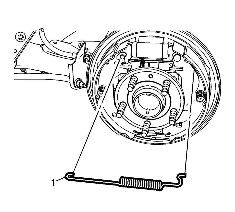
- Remove the upper brake shoe return spring (1).
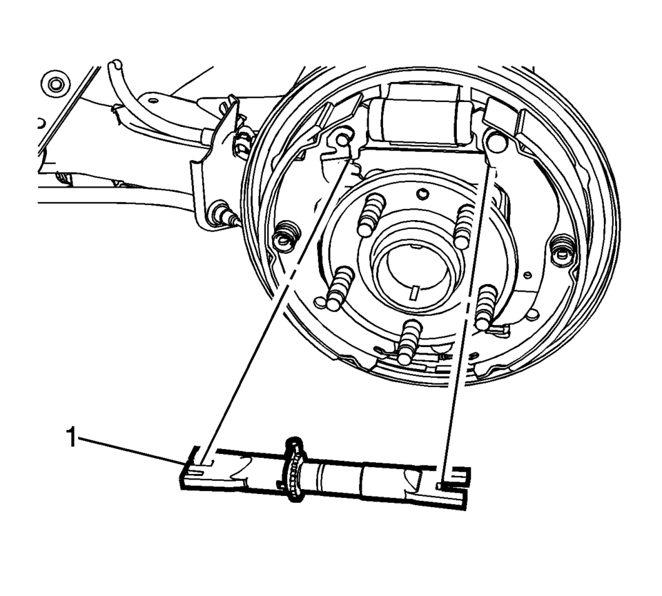
- Remove brake shoe adjuster (1).
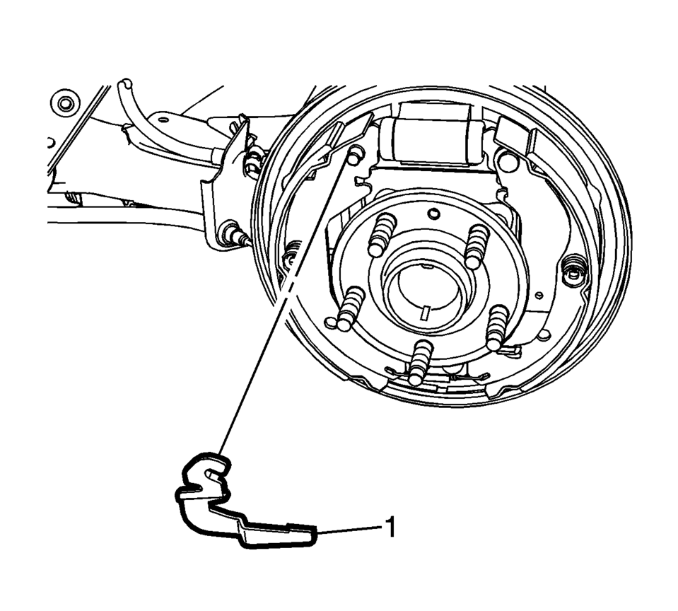
- Remove the brake shoe adjuster actuator lever (1).
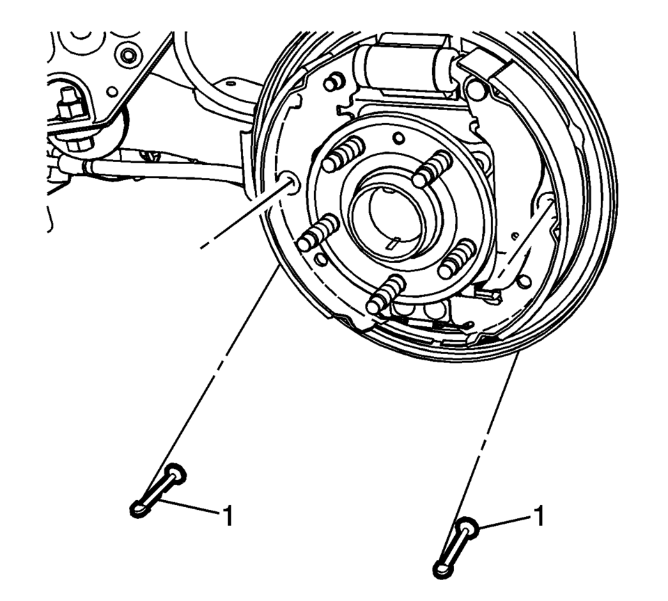
- Remove the brake shoe hold down spring and cup assemblies (1) by compressing the spring and rotating the assembly 1/4 turn.
- Remove the hold down spring and cup assembly pins (1).
- Spread the top of the brake shoe assembly (1) and lift the assembly over the wheel hub.
- Release the park brake actuator lever from the park brake cable eyelet.
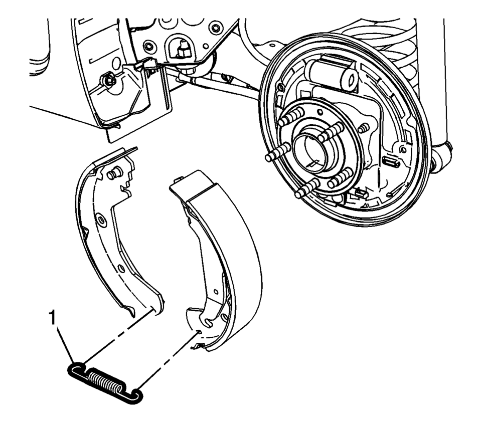
- Remove the lower brake shoe return spring (1).
- Inspect the drum brake hardware and replace any components, as necessary. Refer to Drum Brake Hardware Inspection.
Warning:
Refer to Brake Dust Warning.


- Installation Procedure
-
- Clean the drum brake backing plate of any dirt and debris.
- Apply a light coat of high temperature brake lubricant to the brake drum backing plate shoe contact surfaces.
- Install the lower brake shoe return spring (1).
- Install the park brake actuator lever to the park brake cable eyelet.
- Spread the top of the brake shoe assembly (1) and lift the assembly over the wheel hub.
- Position the brake shoe assembly to the drum brake backing plate.
- Install the hold down spring and cup assembly pins (1).
- Install the brake shoe hold down spring and cup assemblies (1) by compressing the spring and rotating the assembly 1/4 turn.
- Install the brake shoe adjuster actuator lever (1).
- Install brake shoe adjuster (1).
- Install the upper brake shoe return spring (1).
- Adjust the drum brakes. Refer to Drum Brake Adjustment.
- Install the brake drum. Refer to Brake Drum Replacement.
- Install the tire and wheel assembly. Refer to Tire and Wheel Removal and Installation.
 Drum Brake Hardware Inspection
Warning: Refer to Brake Dust Warning.
Visually inspect the drum brake upper return spring (1) for the following
conditions:
Excessive corrosion
Excessive stretchin ...
 Drum Brake System Description and Operation
System Component Description
The drum brake system consists of the following:
Drum Brake Shoes
Applies mechanical output force, from hydraulic brake wheel cylinders,
to frict ...
Other materials:
Rear Compartment Courtesy Lamp Replacement (Sedan)
Rear Compartment Courtesy Lamp Replacement
Callout
Component Name
1
Rear Compartment Courtesy Lamp Assembly
Procedure
Use the appropriate trim tool in order to release the lamp assembly
from the rear quarter ...
Front Side Door Window Switch Bezel Replacement (Left Side)
Front Side Door Window Switch Bezel Replacement
Callout
Component Name
Preliminary Procedure
Remove the front side door trim. Refer to Front Side Door Trim Replacement.
1
Front Side Door Window S ...
Secondary Air Injection Pump Removal
Disconnect the secondary air injection pump pipe (3). Refer to Plastic Collar
Quick Connect Fitting Service.
Remove the secondary air injection pump nut (2) and the 2 secondary air
injection pump bolts (4).
Remove the secondary air injection pump (1 ...

0.0058