
Chevrolet Sonic Owner's Manual: Engine Compartment Overview
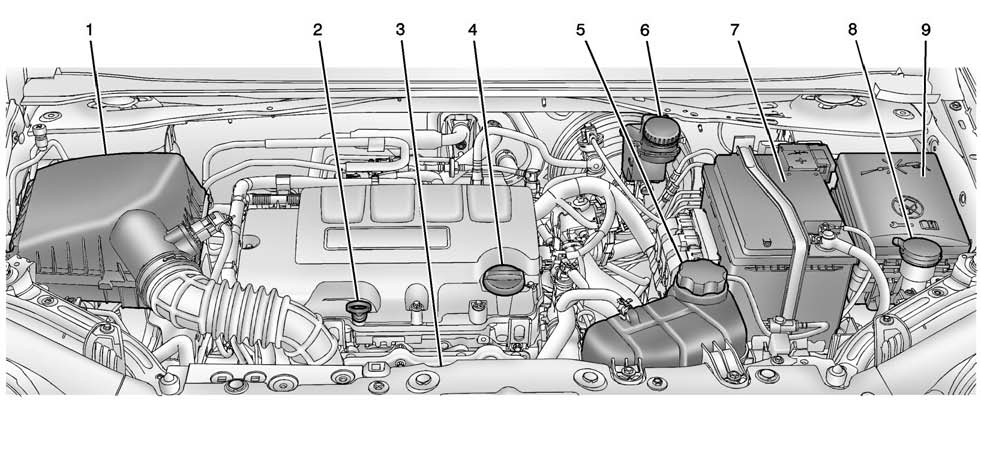
1.4L L4 Engine
1. Engine Air Cleaner/Filter.
2. Engine Oil Dipstick. See Engine Oil.
3. Engine Cooling Fan (Out of View). See Cooling System.
4. Engine Oil Fill Cap. See Engine Oil.
5. Engine Coolant Surge Tank and Pressure Cap. See Cooling System.
6. Brake/Clutch Fluid Reservoir. See Brakes and Hydraulic Clutch.
7. Battery.
8. Windshield Washer Fluid Reservoir. See Washer Fluid.
9. Engine Compartment Fuse Block.
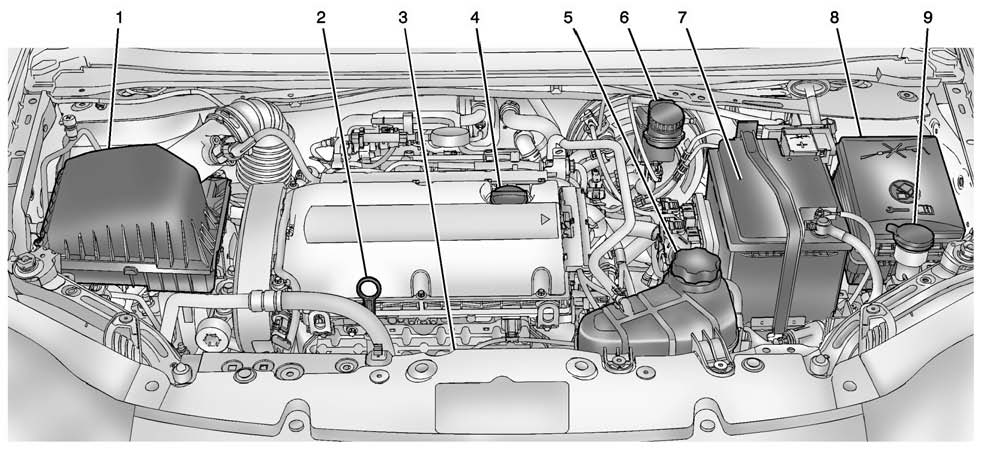
1.8L L4 Engine
1. Engine Air Cleaner/Filter.
2. Engine Oil Dipstick. See Engine Oil.
3. Engine Cooling Fan (Out of View). See Cooling System.
4. Engine Oil Fill Cap. See Engine Oil.
5. Engine Coolant Surge Tank and Pressure Cap. See Cooling System.
6. Brake/Clutch Fluid Reservoir. See Brakes and Hydraulic Clutch.
7. Battery.
8. Engine Compartment Fuse Block.
9. Windshield Washer Fluid Reservoir. See Washer Fluid.
 Hood
Hood
To open the hood:
1. Pull the hood release handle inside the vehicle. It is located on the lower
left side of the instrument panel.
2. Go to the front of the vehicle and move the secondary hoo ...
 Engine Oil
To ensure proper engine performance and long life, careful attention must be
paid to engine oil. Following these simple, but important steps will help protect
your investment:
Always use engin ...
Other materials:
Vehicle Personalization
Personalization Menu (Radio without
Touchscreen)
Use the audio system controls to access the personalization menus for customizing
vehicle features.
The following are all possible personalization features. Depending on the
vehicle, some may not be available.
CONFIG (Confi ...
Rear Seat Back Cushion Removal and Installation (60%)
Rear Seat Back Cushion Removal and Installation
Callout
Component Name
Preliminary Procedure
Remove the rear seat cushion. Refer to Rear Seat Cushion Removal
and Installation.
Remove the rear seat center retractor side be ...
Reverse (Gen 2)
When the gear selector lever is moved to the Reverse (R) position (from the Park
position) the normally-low 35R pressure control solenoid is commanded ON and the
following changes occur in the transmission? hydraulic and electrical systems:
3-5-Reverse Clutch Applies
Manual Valve
...

0.0056