Chevrolet Sonic Repair Manual: Evaporative Emission Canister Replacement
- Removal Procedure
-
- Raise and support the vehicle. Refer to Lifting and Jacking the Vehicle.
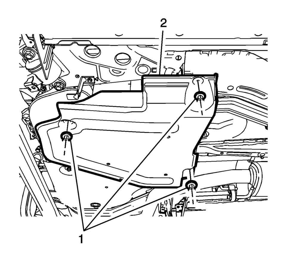
- Remove the EVAP canister cover fasteners (1) and cover (2).
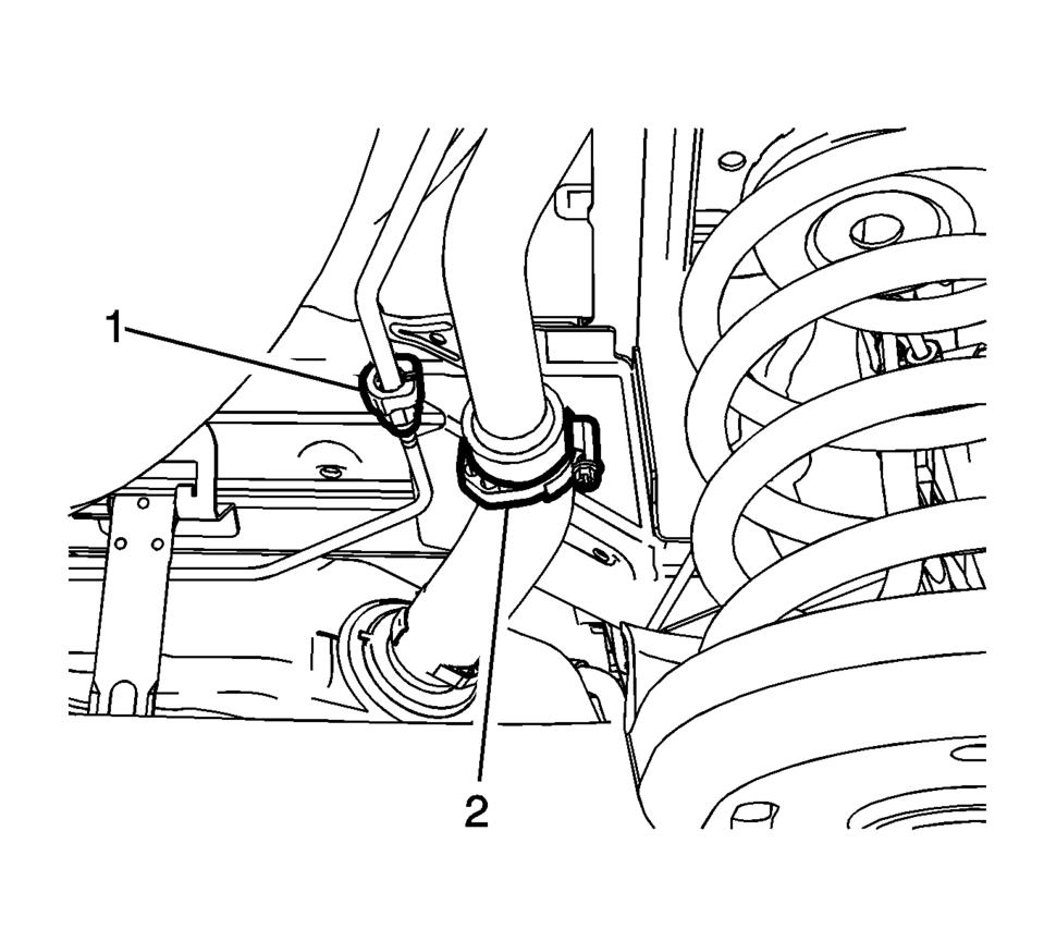
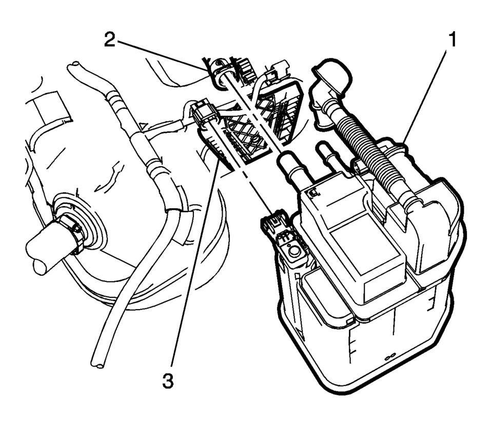
- Remove the evaporative emissions fill vent pipe connector(1) and loosen
the fuel filler hose clamp (2).
If the fuel level is over half filled, refer to Fuel Tank Draining.
- Place a suitable adjustable jack under the fuel tank.
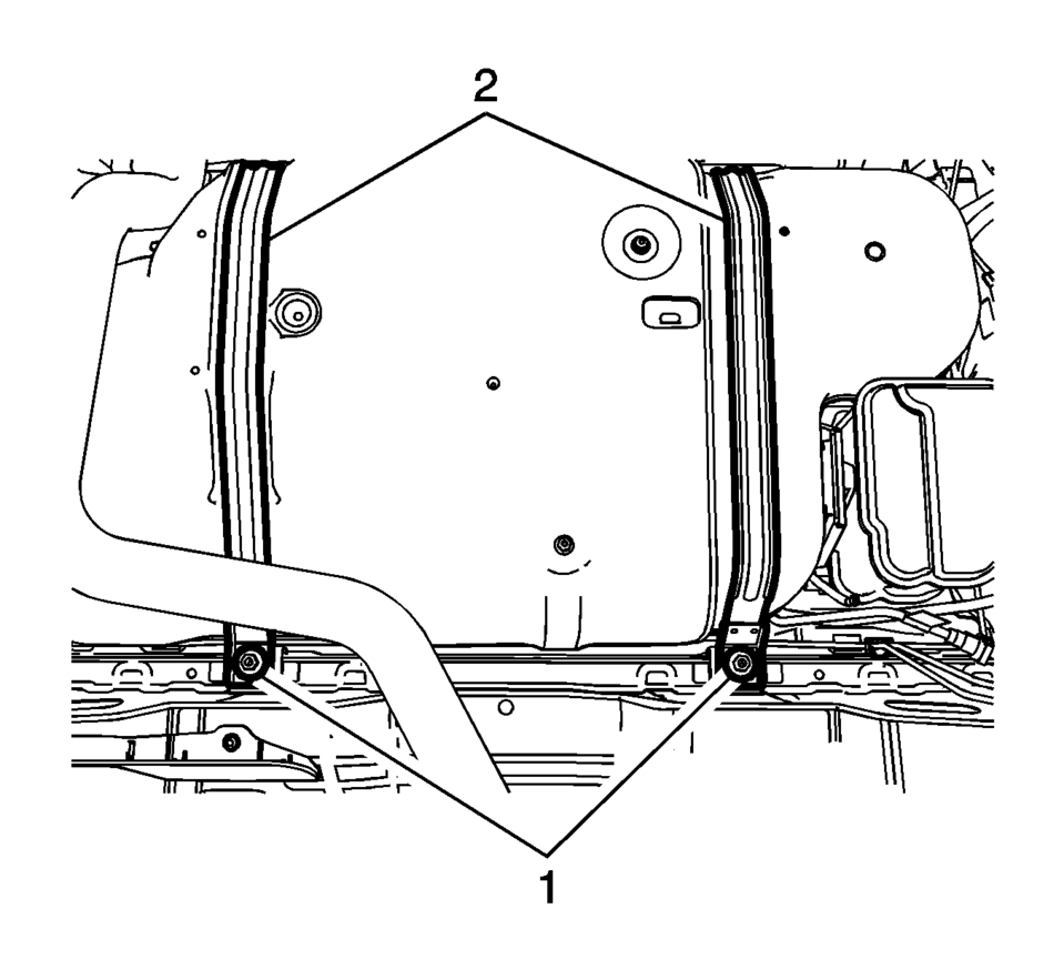
- Remove the 2 fuel tank strap bolts (1).
- Remove the 2 fuel tank straps (2).
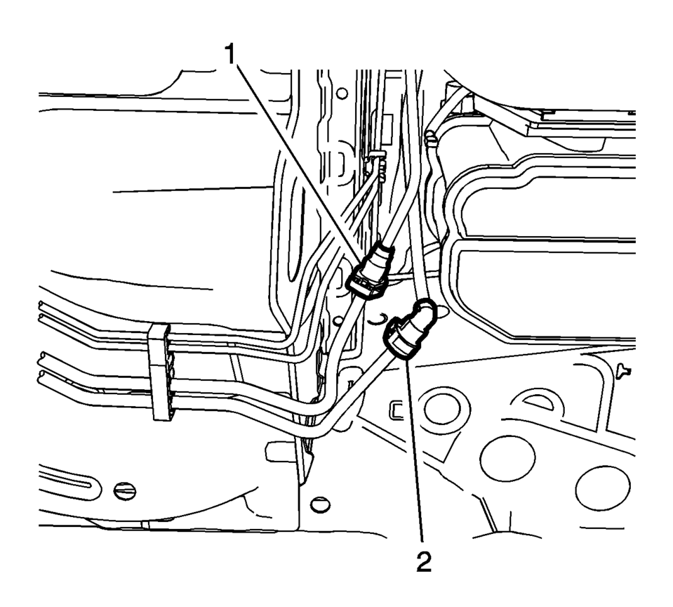
- Disconnect the fuel feed (1) and the evaporative emissions pipe (2).
- Lower the fuel tank to a height where the evaporative emission canister is easily accessible.
- Disconnect the fuel tank vent pipe (2).
- Disconnect the evaporative emission canister wiring harness connectors.
- Disconnect the evaporative emission canister purge pipe (4).
- Remove the evaporative emission canister (1) from the evaporative emission canister bracket (3).
Warning:
Do not breathe the air through the EVAP component tubes or hoses. The fuel vapors inside the EVAP components may cause personal injury.
Note:
Do not remove the fuel tank filler hose when the fuel tank is over half filled with fuel.
Warning:
To help avoid personal injury, always use jack stands when you are working on or under any vehicle that is supported only by a jack.
Caution:
When you are jacking or lifting a vehicle at the frame side rails or other prescribed lift points, be certain that the lift pads do not contact the catalytic converter, the brake pipes or the fuel lines. If such contact occurs, vehicle damage or unsatisfactory vehicle performance may result.
Note:
Closely watch parts like pipes or hoses that are still installed to the fuel tank. If lowering the fuel tank slightly does not provide enough access to remove the fuel tank, refer to Fuel Tank Replacement.
Warning:
Always wear safety goggles when working with fuel in order to protect the eyes from fuel splash.
- Installation Procedure
-
- Install the evaporative emission canister (1) to the evaporative emission canister bracket (3).
- Connect the evaporative emission canister purge pipe (4).
- Connect the evaporative emission canister wiring harness plug.
- Connect the fuel tank vent pipe (2).
- Raise the fuel tank to its original position.
- Connect the fuel feed (1) and the evaporative emissions pipes (2).
- Install the 2 fuel tank straps (1).
- Install the 2 fuel tank strap bolts (2) and tighten to 23 Y (17 lb ft)
.
- Remove the adjustable jack.
- Connect the evaporative emissions fill vent pipe connector(1).
- Install the clamp (2) and tighten to 3 Y (27 lb in)
.
- Install the EVAP canister cover (2).
- Lower the vehicle.
Caution:
Refer to Fastener Caution.
 Fuel and Evaporative Emission Pipe Warning
Warning: In order to reduce the risk of fire and personal injury observe
the following items:
Replace all nylon fuel pipes that are nicked, scratched or damaged during
installation, d ...
 Evaporative Emission Canister Replacement (Steel Tank)
Removal Procedure
Remove the evaporative emission canister bracket fasteners (1).
Disconnect the purge solenoid valve electrical connector (1).
Disconn ...
Other materials:
Heater Core Outlet Tube Replacement
Heater Core Outlet Tube Replacement
Callout
Component Name
Preliminary Procedures
Remove the Heater and Air Conditioning Evaporator and Blower Module.
Refer to Heater and Air Conditioning Evaporator and Blower Module Removal
...
I-FCW system limitations
Illustration A
Illustration B
Illustration C
Illustration D
WARNING
The following limitations apply to the Nissan Armada I-FCW system. Ignoring
these limitations may result in serious injury or fatal accidents.
The Nissan Armada I-FCW system cannot detect every object or v ...
Maintenance schedules
Basic information
To ensure your Nissan Armada delivers reliable performance, optimal safety, and
long-term efficiency, NISSAN provides two distinct maintenance schedules tailored
to different driving conditions. These schedules are carefully designed to cover
both mileage and time intervals, ...

0.0055