Chevrolet Sonic Repair Manual: Front and Rear Suspension Modification Kit Installation
Installation Instruction Part Number
23158166
23158167
Tools Required
CH 49375 Strut Rod Nut Socket
For equivalent regional tools, refer to Vehicle Service Manual.
- Front Strut Removal Procedure
-
- Remove the air inlet grille panel. Refer to Vehicle Service Manual.
- Raise and support the vehicle. Refer to Vehicle Service Manual.
- Remove the front tire and wheel assembly. Refer to Vehicle Service Manual.
- Remove the stabilizer shaft link from the front strut assembly. Refer to Vehicle Service Manual.
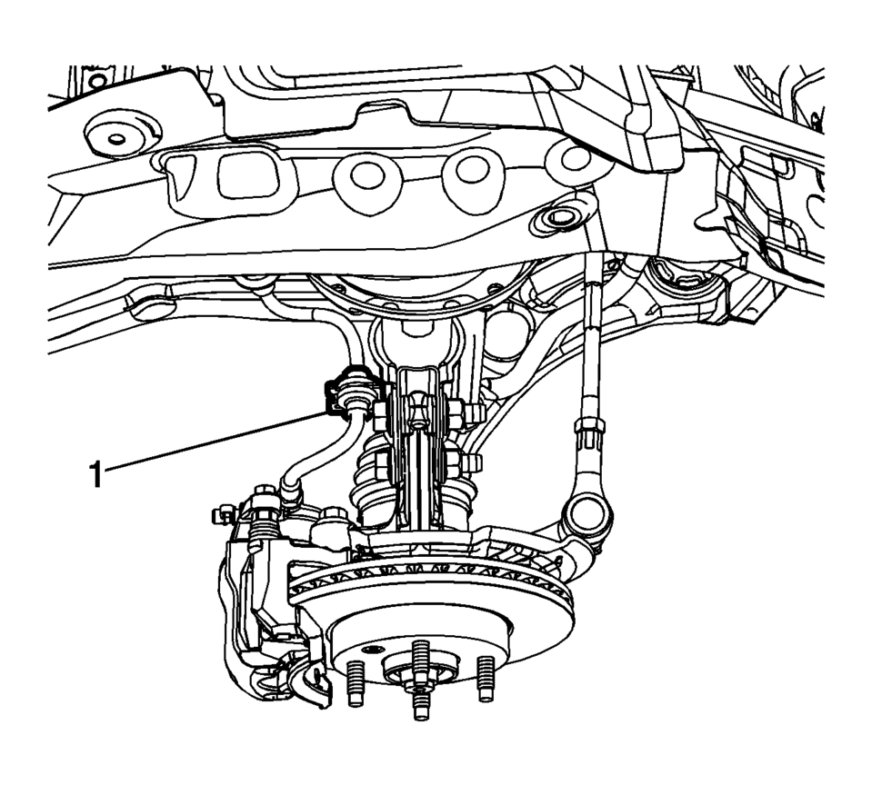
- Remove the front brake hose (1) from the front strut assembly.
- Remove the speed sensor wring harness from the front strut assembly, if needed.
- Remove the outer tie rod end from the steering knuckle. Refer to Vehicle Service Manual.
- Support the lower control arm with a jack stand.
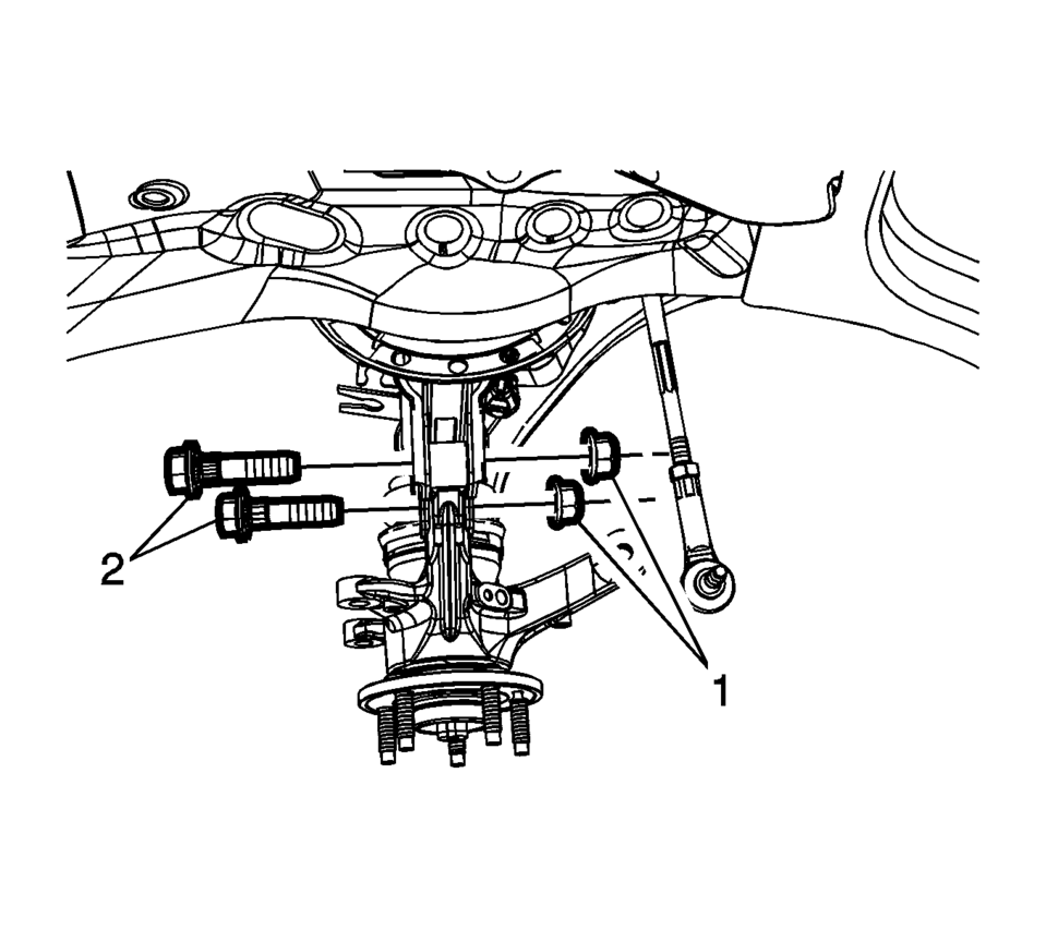
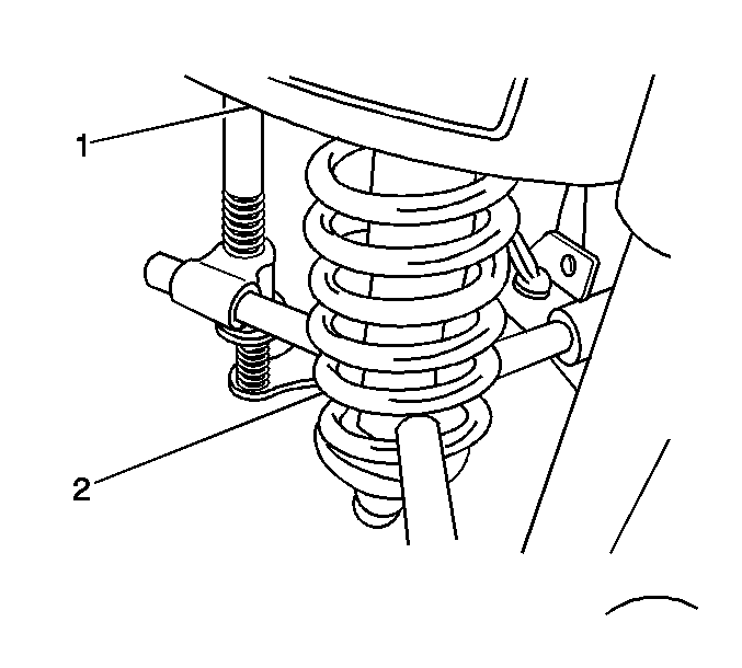
- Remove the front strut nut (1) and the bolt (2) from the front strut.
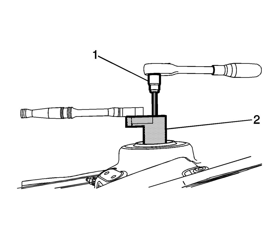
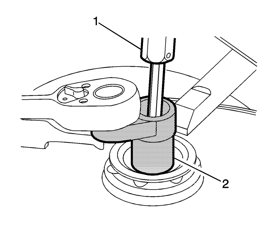
- Using the CH 49375 socket (2) and the proper size Torx® wrench, loosen the front strut nut.
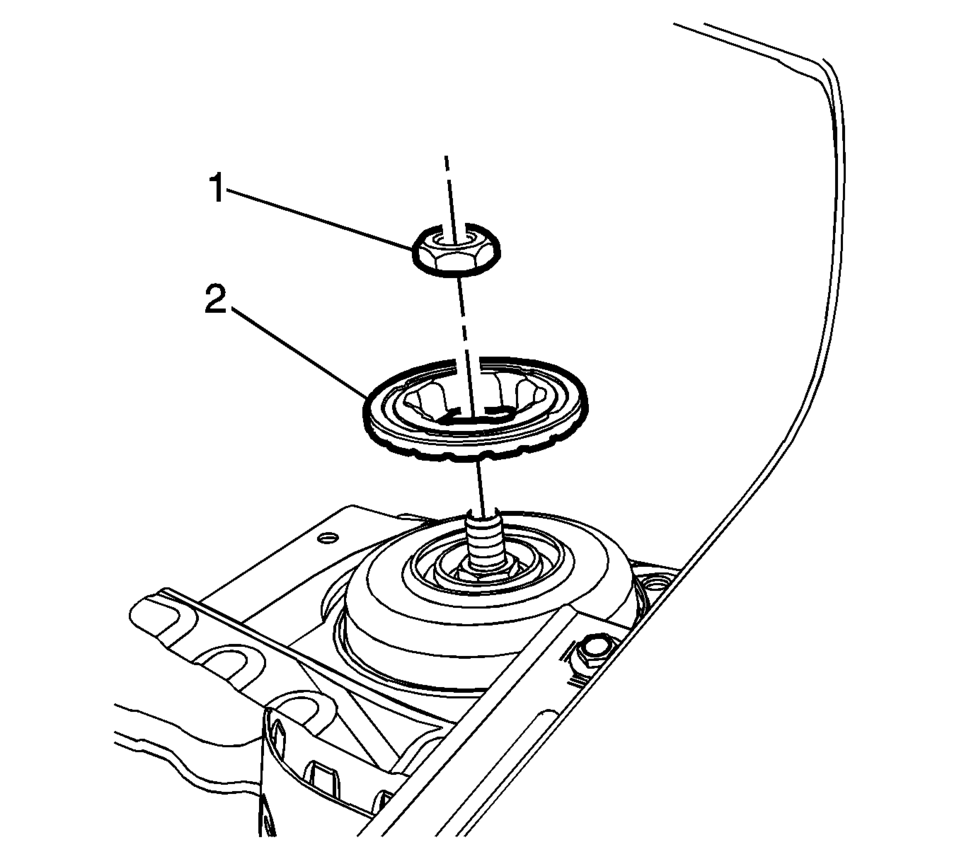
- Remove the front strut nut (1) and the retaining plate (2).
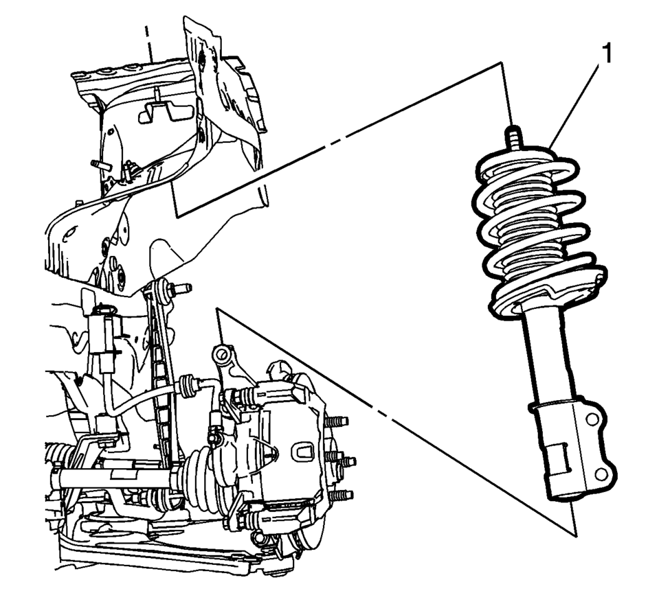
- Remove the front strut assembly from the vehicle (1).
- Front Strut Disassembly Procedure
-
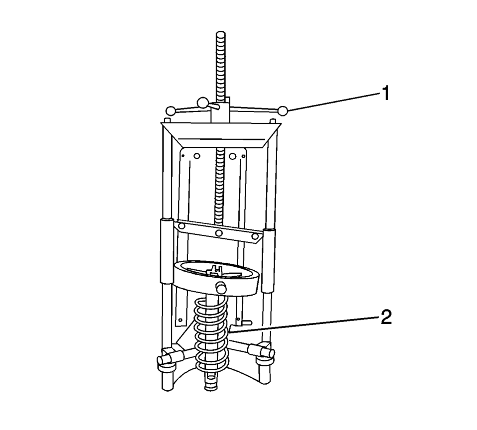
- Install the strut assembly (2) in a suitable spring compressor (1) and compress the front spring.
- Use a suitable bit (1) and socket (2) to loosen the front suspension strut mount nut.
- Slowly loosen the spring compressor (2) to remove the front suspension strut components to be serviced.
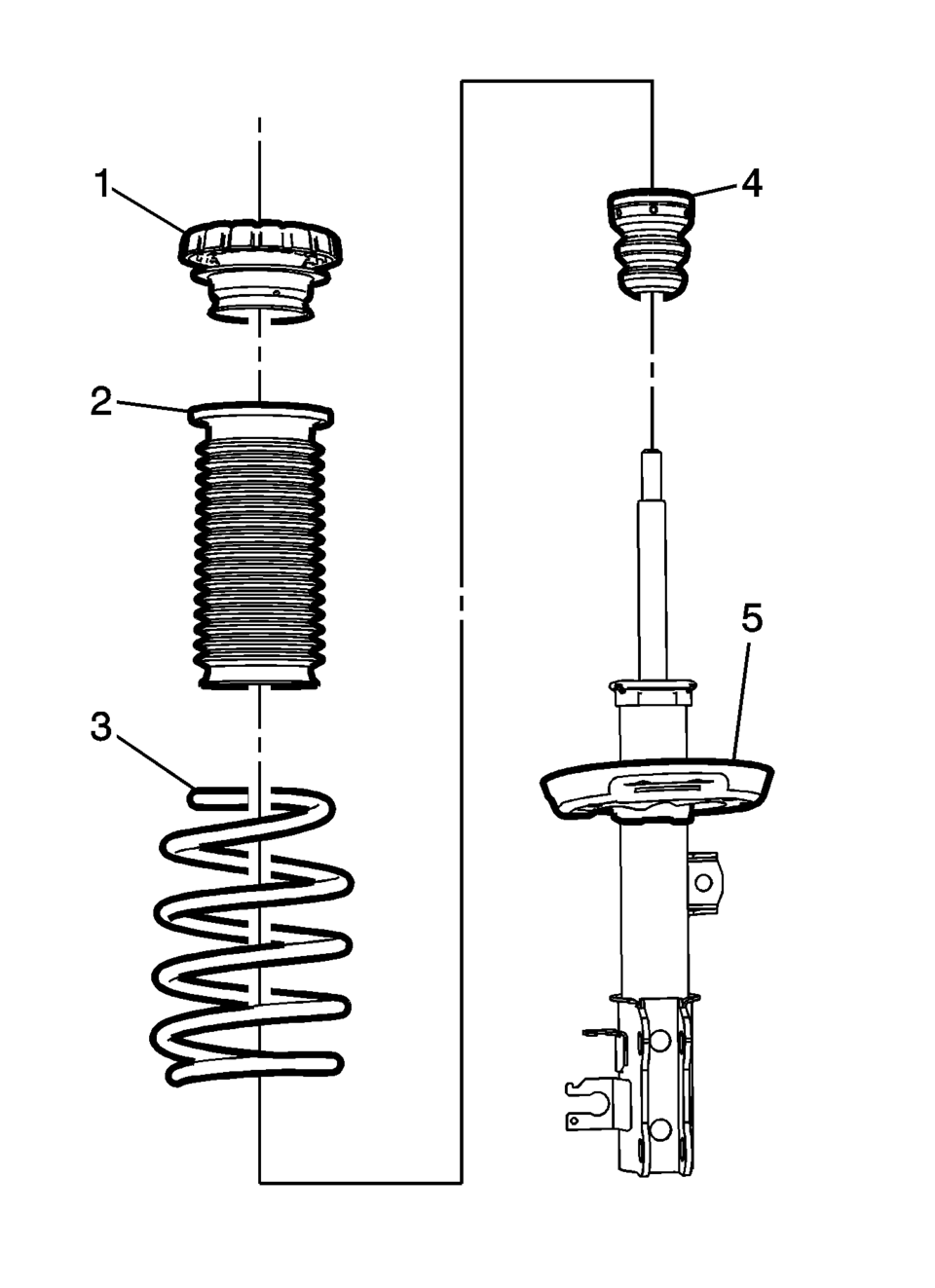
- Remove the front suspension strut mount assembly (1), front spring insulator (2), front spring (3), front suspension strut bumper (4) and the front strut (5) from the spring compressor.
Note:
The spring is compressed when the strut moves freely.
(((((((l(((((((((((i
- Front Strut Assembly Procedure
-
- Install the front suspension strut (5), front suspension strut bumper (4), front spring (3), front spring insulator (2) and the front suspension strut mount assembly (1) in the spring compressor.
- Use the spring compressor (1) to compress the front spring (2).
- Install the front suspension strut mount nut and tighten as much as possible by hand.
- Use a suitable bit (1) and socket (2) to tighten the front suspension
strut mount nut to 65 Y (48 lb ft)
.
- Remove the strut assembly from the spring compressor.
(((((((l(((((((((((i
Caution:
Use the correct fastener in the correct location. Replacement fasteners must be the correct part number for that application. Fasteners requiring replacement or fasteners requiring the use of thread locking compound or sealant are identified in the service procedure. Do not use paints, lubricants, or corrosion inhibitors on fasteners or fastener joint surfaces unless specified. These coatings affect fastener torque and joint clamping force and may damage the fastener. Use the correct tightening sequence and specifications when installing fasteners in order to avoid damage to parts and systems.
- Front Strut Installation Procedure
-
- Position the front strut assembly (1) in the vehicle.
- Install the front strut nut (1) and the retaining plate (2).
- Using the CH 49375 socket (2) and the proper size Torx® wrench
to hold the strut shaft, tighten the nut to 65 Y (48 lb ft)
.
- Install the front strut nut (1) and the bolt (2) from the front strut
and tighten the nut to 110 Y (82 lb ft)
.
- Install the stabilizer shaft link in the front strut assembly. Refer to Refer to Vehicle Service Manual.
- Remove the jack stand from the lower control arm.
- Install the outer tie rod end in the steering knuckle. Refer to Refer to Vehicle Service Manual.
- Install the speed sensor wiring harness on the front strut assembly, if needed.
- Install the front brake hose (1) on the front strut assembly.
- Install the front tire and wheel assembly. Refer to Refer to Vehicle Service Manual.
- Remove the support and lower the vehicle.
- Install the air inlet grille panel. Refer to Refer to Vehicle Service Manual.
- Rear Shock Absorber Removal Procedure
-
- Raise and support the vehicle. Refer to Vehicle Service Manual.
- Remove the rear tire and wheel assembly. Refer to Vehicle Service Manual.
- Support the rear axle with a hydraulic jack.
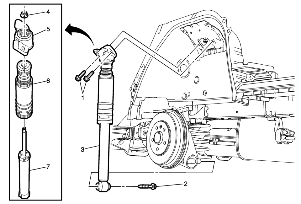
- Remove the rear shock absorber upper bolts (1).
- Remove the rear shock absorber lower bolt (2).
- Remove the rear shock absorber assembly (3) from the vehicle. Rear Shock Absorber Disassembly Procedure
- Remove shock absorber nut (4) from shock (7).
- Remove shock absorber mount (5).
- Remove shock absorber bumper (6).
- Rear Spring, Insulator, and Jounce Bumper Removal and Installation Procedure
-
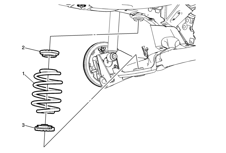
- Lower the rear axle and remove the rear spring (1) from the upper (2) and lower (3) rear spring insulators.
- Ensure that the lower rear spring insulator (3) is properly seated in the rear axle.
- Ensure that the upper rear spring insulator (2) is properly seated in the rear frame rail.
- Install the rear spring (1) to the upper and lower rear spring insulators.
Note:
Note the position of the rear spring in relationship to the insulators.
- Rear Shock Absorber Assembly Procedure
-
- Install shock absorber bumper (6) to the rear shock absorber (7).
- Install the shock absorber mount (5).
- Install the shock absorber nut (4) and tighten the nut to 25 Y (18 lb ft)
.
Rear Shock Absorber Installation Procedure - Install the rear shock absorber assembly (3) to the vehicle.
- Install the rear shock absorber lower bolt (2).
Tighten
First Pass: 100 Y (74 lb ft).Tighten
Second Pass: plus 90 degrees
.
- Install the rear shock absorber upper bolts (1) and tighten the bolts
to 58 Y (43 lb ft)
.
- Install the rear tire and wheel assembly. Refer to Vehicle Service Manual.
- Remove support and lower the vehicle.
 Front Suspension Description and Operation
The front suspension has 2 primary purposes:
Isolate the driver from irregularities in the road surface.
Define the ride and handling characteristics of the vehicle.
The front suspension ab ...
 Rear Axle Replacement
Removal Procedure
Raise and support the vehicle. Refer to Lifting and Jacking the Vehicle.
Remove the tires and wheel assembly. Refer to Tire and Wheel Removal
and Installation ...
Other materials:
Disc Brake System Description and Operation
System Component Description
The disc brake system consists of the following components:
Disc Brake Pads
Applies mechanical output force from the hydraulic brake calipers to
friction surfaces of brake rotors.
Disc Brake Rotors
Uses mechanical output force ap ...
Air Conditioning Compressor and Condenser Hose Replacement (LUV)
Removal Procedure
Recover the refrigerant. Refer to Refrigerant Recovery and Recharging.
Remove the drivetrain and front suspension frame skid plate if equipped.
Refer to Drivetrain and Front Suspension Frame Skid Plate Replacement.
Remove the front fascia assembly. Re ...
Drive Range, First Gear Engine Braking (Gen 2)
Note: Some models of the 6T30/40/45/50 automatic transmission are equipped with
an electric auxiliary fluid pump for use in hybrid vehicles (BAS+). Hybrid vehicles
do not require internal combustion engine (ICE) operation at all times. After a
successful engine start, the hybrid powertrain con ...

0.0045