
Chevrolet Sonic Repair Manual: Front Disc Brake Pads Replacement
- Removal Procedure
-
Warning:
Refer to Brake Dust Warning.
Note:
Always replace disc brake pads in axle sets.
- Inspect the fluid level in the brake master cylinder reservoir.
- If the brake fluid level is midway between the maximum-full point and the minimum allowable level, no brake fluid needs to be removed before proceeding.
- If the brake fluid level is higher than midway between the maximum-full point and the minimum allowable level, remove brake fluid to the midway point before proceeding.
- Raise and support the vehicle. Refer to Lifting and Jacking the Vehicle.
- Remove the tire and wheel assembly. Refer to Tire and Wheel Removal and Installation.
- Place a large C-clamp over the brake caliper body and against the outer brake pad.
- Using the C-clamp, compress the brake caliper piston fully into the brake caliper bore.
- DO NOT use any air tools to remove or install the guide pin bolts. Use hand tools ONLY.
- Install an open end wrench to hold the caliper guide pin in line with the brake caliper while removing or installing the caliper guide pin bolt. DO NOT allow the open end wrench to come in contact with the brake caliper. Allowing the open end wrench to come in contact with the brake caliper will cause a pulsation when the brakes are applied.
- Using a backup wrench to hold the brake caliper guide pin stationary, remove the lower brake caliper guide pin bolt (1).
- Rotate the brake caliper upward and support with heavy mechanics wire or equivalent.
- Remove the inner brake pad (1).
- Remove the outer brake pad (2).
- Remove the upper and lower brake pad springs (1).
- If installing new brake pads, discard the brake pad springs.
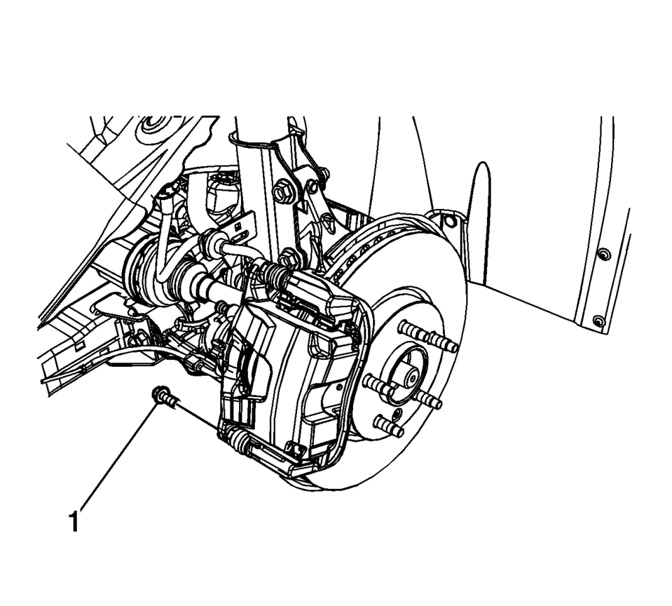
Note:
Caution:
Support the brake caliper with heavy mechanic wire, or equivalent, whenever it is separated from its mount and the hydraulic flexible brake hose is still connected. Failure to support the caliper in this manner will cause the flexible brake hose to bear the weight of the caliper, which may cause damage to the brake hose and in turn may cause a brake fluid leak.
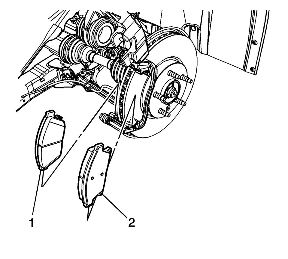
Note:
Note the location of the brake pad wear sensor for correct installation.
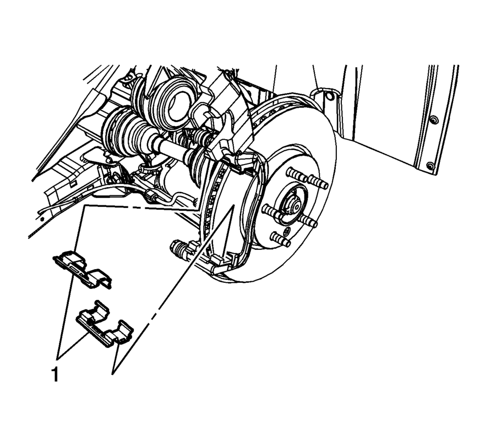
- Installation Procedure
-
- Thoroughly clean the contact surfaces of the brake caliper bracket of any corrosion or debris.
- Install the upper and lower brake pad springs (1).
- Install the inner brake pad (1).
- Install the outer brake pad (2).
- Position the brake caliper over the brake pads and to the caliper bracket.
- Using a backup wrench to hold the brake caliper guide pin stationary,
install the lower brake caliper guide pin bolt (1) and tighten to 28 Y
(21 lb ft)
.
- Install the tire and wheel assembly. Refer to Tire and Wheel Removal and Installation.
- With the engine OFF, gradually apply the brake pedal to approximately 2/3 of its travel distance.
- Slowly release the brake pedal.
- Wait 15 seconds, then repeat steps 8-9 until a firm brake pedal is obtained. This will properly seat the brake caliper piston and brake pads.
- Fill the master cylinder reservoir. Refer to Master Cylinder Reservoir Filling.
- Burnish the brake pads and rotors. Refer to Brake Pad and Rotor Burnishing.
Note:
If installing new brake pads, install new brake pad springs.
Note:
Note the location of the brake pad wear sensor for correct installation.
Caution:
Refer to Fastener Caution.
 Brake Pad and Rotor Burnishing
Warning: Road test a vehicle under safe conditions and while obeying
all traffic laws. Do not attempt any maneuvers that could jeopardize vehicle
control. Failure to adhere to these precautio ...
 Rear Disc Brake Pads Replacement
Removal Procedure
Warning: Refer to Brake Dust Warning.
Note: Always replace disc brake pads in axle sets.
Inspect the fluid level in the brake master cylinder reservo ...
Other materials:
Rear Compartment Lid Applique Replacement
Rear Compartment Lid Applique Replacement
Callout
Component Name
Preliminary Procedure
Open and support the rear compartment lid.
Remove the rear compartment lid inner panel trim. Refer to Rear
Compartment Lid Inner Panel ...
Fuel Tank Fuel Pump Module Replacement
Special Tools
EN-48279 Fuel Sender Lock Ring Tool
For equivalent regional tools, refer Special Tools.
Removal Procedure
Relieve the fuel system pressure. Refer to Fuel Pressure Relief
Remove the fuel tank. Refer to Fuel Tank Replacement.
Disconnect the electrical c ...
Active sound enhancement
NOTE:
To ensure the active sound enhancement system in the Nissan Armada operates
at its best performance, follow these important guidelines:
Do not block or cover the speakers, as this may distort or reduce sound
quality.
Avoid modifying or replacing the original speaker components inst ...

0.0082