Chevrolet Sonic Repair Manual: Front Side Door Lock Cylinder Coding (Free Wheeling)
Special Tools
BO-49753 Assembly Tool
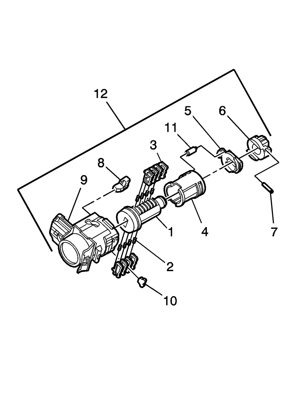
The door lock cylinder uses 8 of the 8 cut positions. The tumbler positions are staggered from side to side, 4 on one side and 4 on the other, are not self-retaining, and are not snap in.
- Hold the door lock cylinder (1) so the side with the 4 tumbler spring pockets faces up, pocket nearest to the cylinder head.
- Insert the tumbler springs (2) into the 4 spring pockets. This side uses left tumblers.
- Install the tumbler (3) for key cut position one in the slot nearest to the front of the lock cylinder. Install the remaining tumblers, key cut positions 3, 5, and 7, following the key code and same process. Press the tumblers in place until they are secure.
- Check the correct loading of the tumblers by inserting the key into the cylinder. All tumblers should be flush with the lock cylinder body.
- Turn the cylinder so the side with the 4 tumbler spring wells faces up. This side uses right tumblers.
- Insert the tumbler springs into the 4 spring pockets.
- The first tumbler closest to the front of the lock cylinder to be loaded will be the second key cut position, the second number in the key code. Install the remaining tumblers for the key cut positions 4, 6, and 8. Press the tumblers in place until they are secure.
- Check the correct loading of the tumblers by inserting the key into the cylinder. All tumblers should be flush with the lock cylinder body.
- Insert the key and lightly lubricate the cylinder body diameter and tumbler surfaces and a small amount in the head of the cylinder using the supplied grease.
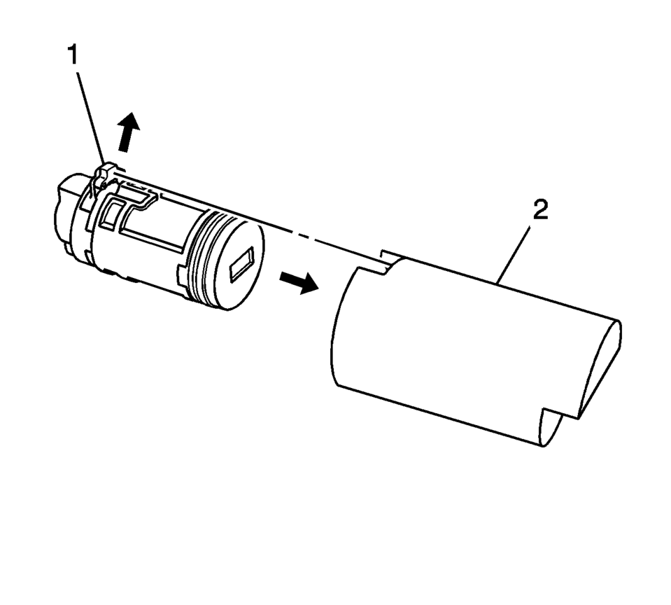
- Insert the sleeve (4) onto the cylinder assembly.
- Insert the clutch (5) and driver (6) onto the cylinder (1).
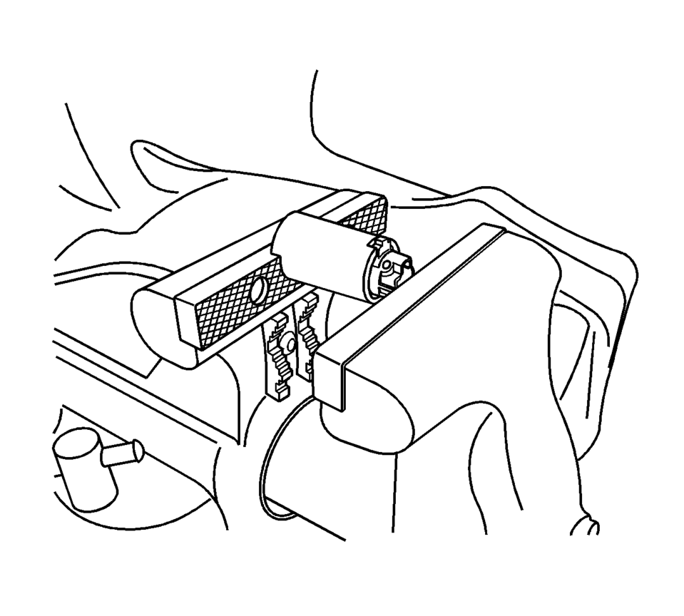
- Load the cylinder into the BO-49753 assembly tool so that the clutch (1) indexes with the notch in the opening of the tool (2).
- Load the assembly tool with the lock cylinder into a vice and tighten the vice ONLY enough to hold the tool and lock the cylinder in place.
- Insert the roll pin (7) into the driver (6) and install it using a 1/16 inch pin punch.
- Insert the buffer (8) in the case (9), verify the buffer is properly seated.
- Install the free wheel pin (11) in the sleeve (4) and clutch (5) and insert the assembly into the case (9).
- With the lock cylinder assembly installed in the case (9), install the retainer (10) and stake the retainer in place using a small punch and hammer to peen the case material onto the exposed ends of the installed retainer (10).
- Insert the key into the lock and function the lock to check for proper assembly and smooth operation.
Note:
All lock cylinders for side milled keys have right and left tumblers. The location of the tooth of the tumbler determines whether it is right of left. Illustrations in this procedure show the right tumblers on the top and the left tumblers on the bottom. All tumblers are marked 1R, 1L, 2R, or 2L. The number being cut depth and the letter meaning right or left.
 Remote Control Door Lock Receiver Replacement
Remote Control Door Lock Receiver Replacement
Callout
Component Name
Preliminary Procedure
Remove the windshield outside moistu ...
 Front Side Door Lock Cylinder Coding (Non Free Wheeling)
The door lock cylinder uses 8 of the 8 cut positions. The tumbler positions are
staggered from side to side, 4 on one side and 4 on the other, are not self-retaining,
and are not snap in ...
Other materials:
Front Side Door Upper Hinge and Lower Hinge Replacement
Front Side Door Upper Hinge and Lower Hinge Replacement
Callout
Component Name
1
Front Side Door Upper Hinge to Body Bolt (Qty:?€‰2)
Caution: Refer to Fastener Caution.
Procedures
Before removing ...
Rear Seat Back Cushion Removal and Installation (40%)
Rear Seat Back Cushion Removal and Installation
Callout
Component Name
Preliminary Procedure
Remove the rear seat cushion. Refer to Rear Seat Cushion Removal
and Installation.
Remove the rear seat back cushion bolster. Re ...
3-5-Reverse and 4-5-6 Clutch Housing Assemble (6T30/40/45/50 - Gen 2)
Table 1:
4?? Clutch Piston Installation
Table 2:
4?? Clutch Fluid Dam Installation
Table 3:
3? Reverse Clutch Plates Installation
Table 4:
Reluctor Wheel and Piston Installation
Table 5:
4?? Clutch Plates Installation
Table 6:
...

0.0103