Chevrolet Sonic Repair Manual: Front Side Door Lock Cylinder Coding (Non Free Wheeling)
The door lock cylinder uses 8 of the 8 cut positions. The tumbler positions are staggered from side to side, 4 on one side and 4 on the other, are not self-retaining, and are not snap in.
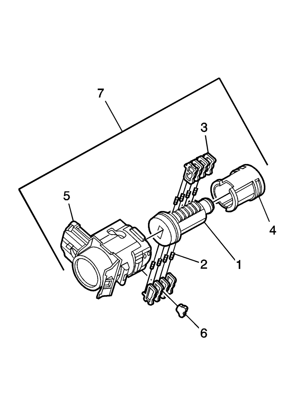
- Hold the door lock cylinder (1) so the side with the 4 tumbler spring pockets faces up, pocket nearest to the cylinder head.
- Insert the tumbler springs (2) into the 4 spring pockets. This side uses left tumblers.
- Install the tumbler (3) for key cut position one in the slot nearest to the front of the lock cylinder. Install the remaining tumblers, key cut positions 3, 5, and 7, following the key code and same process. Press the tumblers in place until they are secure.
- Check the correct loading of the tumblers by inserting the key into the cylinder. All tumblers should be flush with the lock cylinder body.
- Turn the cylinder so the side with the 4 tumbler spring wells faces up. This side uses right tumblers.
- Insert the tumbler springs into the 4 spring pockets.
- The first tumbler closest to the front of the lock cylinder to be loaded will be the second key cut position, the second number in the key code. Install the remaining tumblers for the key cut positions 4, 6, and 8. Press the tumblers in place until they are secure.
- Check the correct loading of the tumblers by inserting the key into the cylinder. All tumblers should be flush with the lock cylinder body.
- Insert the key and lightly lubricate the cylinder body diameter and tumbler surfaces and a small amount in the head of the cylinder using the supplied grease.
- Insert the sleeve (4) onto the cylinder assembly.
- Insert the assembly into the case (5).
- With the lock cylinder assembly installed in the case (5), install the retainer (6) and stake the retainer in place using a small punch and hammer to peen the case material onto the exposed ends of the installed retainer (6).
- Insert the key into the lock and function the lock to check for proper assembly and smooth operation.
Note:
All lock cylinders for side milled keys have right and left tumblers. The location of the tooth of the tumbler determines whether it is right of left. Illustrations in this procedure show the right tumblers on the top and the left tumblers on the bottom. All tumblers are marked 1R, 1L, 2R, or 2L. The number being cut depth and the letter meaning right or left.
 Front Side Door Lock Cylinder Coding (Free Wheeling)
Special Tools
BO-49753 Assembly Tool
The door lock cylinder uses 8 of the 8 cut positions. The tumbler positions are
staggered from side to side, 4 on one side and 4 on the other, are ...
 Front Side Door Lock Cylinder Opening Cover Replacement
Front Side Door Lock Cylinder Opening Cover Replacement
Callout
Component Name
1
Front Side Door Lock Cylinder Opening C ...
Other materials:
Rear Side Door Window Weatherstrip Replacement (Sedan)
Rear Side Door Window Weatherstrip Replacement
Callout
Component Name
Preliminary Procedures
The rear door side window weatherstrip and window is serviced as
one assembly. Refer to Rear Side Door Stationary Window Replacement. ...
Front Wheel Drive Shaft Outer Joint and Boot Replacement
Special Tools
DT-35910 Drive Axle Boot Clamp Pliers
For equivalent regional tools, refer to Special Tools
Disassemble Procedure
Remove the wheel drive shaft from the vehicle. Refer to Front Wheel
Drive Shaft Replacement.
Install the drive axle shaft (1) i ...
Basic information
CAUTION
Always use the Nissan Armada power outlets with the engine running to
prevent battery discharge.
Avoid using the power outlets simultaneously with high electrical loads
such as air conditioning, headlights, or defrosters.
Ensure all connected devices are turned OFF before plugg ...

0.0071