Chevrolet Sonic Repair Manual: Fuel Pump Flow Control Module Replacement
|
Callout |
Component Name |
|---|---|
Preliminary Procedures
|
|
|
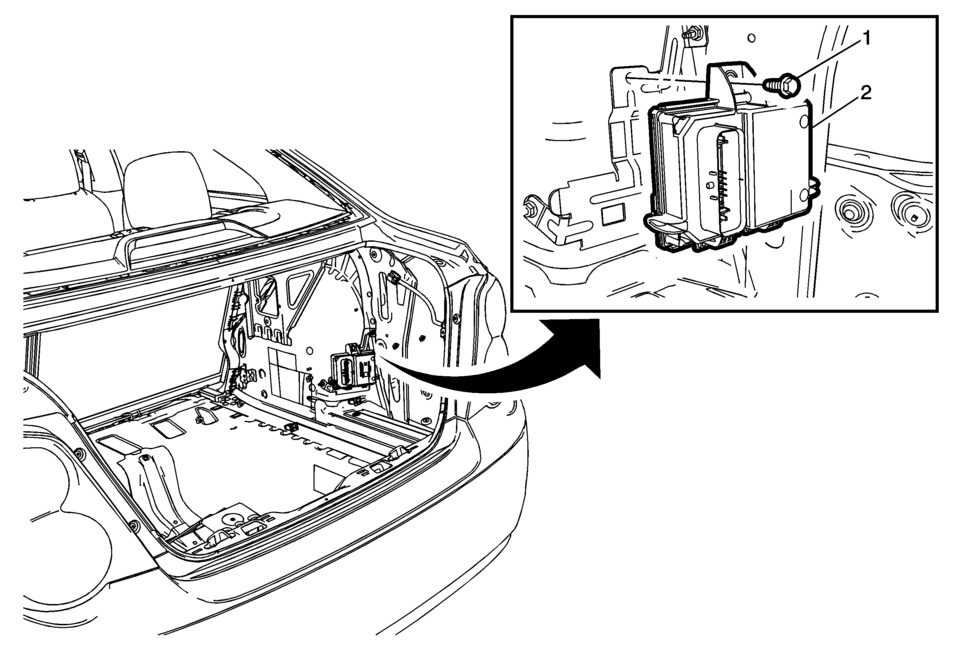
1 |
Fuel Pump Control Module Fastener Caution: Refer to Fastener Caution.
10 Y (89 lb in) |
|
2 |
Fuel Pump Control Module Caution:
|
 Fuel Injector Replacement
Fuel Injector Replacement
Callout
Component Name
Preliminary Procedure
Disconnect battery negative cable. Refer to Battery Negative ...
 Fuel Tank Fuel Pump Module Replacement
Special Tools
EN-48279 Fuel Sender Lock Ring Tool
For equivalent regional tools, refer Special Tools.
Removal Procedure
Relieve the fuel system pressure. Refer to Fuel Press ...
Other materials:
Hood Side Seal Replacement
Hood Side Seal Replacement
Callout
Component Name
1
Hood Side Seal Push-In Retainer (Qty:?€‰6)
2
Hood Side Seal
...
Instrument Panel Insulator Replacement
Instrument Panel Insulator Replacement
Callout
Component Name
Preliminary Procedures
Disable the SIR system. Refer to SIR Disabling and Enabling.
Remove the passenger inflatable restraint instrument panel lower
module ...
Control Solenoid Valve and Transmission Control Module Assembly Inspection
Verify the conditions listed below do not exist. Carefully
inspect the control solenoid valve assembly connectors and pins (1, 2, 4, 6)
for the condition. Repair or replace as necessary.
Damage
Bent pins
Debris
Broken retaining tab
Contamination
Verify there is ...

0.0046