Chevrolet Sonic Repair Manual: Fuel Pump Flow Control Module Replacement
|
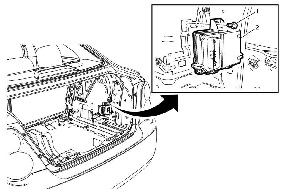
Callout |
Component Name |
|---|---|
Preliminary Procedures
|
|
|
1 |
Fuel Pump Control Module Fastener Caution: Refer to Fastener Caution.
10 Y (89 lb in) |
|
2 |
Fuel Pump Control Module Caution:
|
 Fuel Pressure Relief
Special Tools
EN-34730-91 Pressure Tester
For equivalent regional tools, refer to Special Tools.
Warning: Gasoline or gasoline vapors are highly flammable. A fire
could occur if an ig ...
 Fuel System Cleaning
Note: If the fuel filter is plugged, the fuel tank should be inspected
internally and cleaned if necessary.
Drain the fuel tank. Refer to
Fuel Tank Draining.
Remove the f ...
Other materials:
Instrument Panel Compartment Door Dampener Replacement
Instrument Panel Compartment Door Dampener Replacement
Callout
Component Name
Preliminary Procedure
Remove the instrument panel lower compartment. Refer to Instrument Panel
Lower Compartment Replacement.
1 ...
Body Side Trim Panel Replacement (Sedan)
Body Side Trim Panel Replacement
Callout
Component Name
Preliminary Procedures
Remove rear side door opening floor carpet retainer. Refer to Rear
Side Door Opening Floor Carpet Retainer Replacement.
Remove body rear seat ...
Mirror Adjustment
Exterior Mirrors
Manual Outside Mirrors
Move the control up, down, or side to side to adjust the mirror.
See Manual Mirrors.
Power Outside Mirrors
For vehicles with power outside mirrors:
Select the mirror by moving the selector switch to L for the driver
s ...

0.0063