Chevrolet Sonic Repair Manual: Gear Position Sensor Replacement
|
Callout |
Component Name |
|---|---|
|
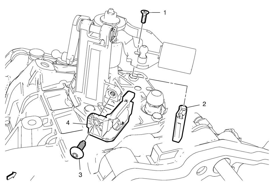
Preliminary Procedure
Unclip the engine control module (ECM) and bracket from the battery tray. |
|
|
1 |
Gear Position Sensor Magnet Bolt Caution: Refer to Fastener Caution.
8 Y (71 lb ft) |
|
2 |
Gear Position Sensor Magnet |
|
3 |
Gear Position Sensor Bolt Tighten
8 Y (71 lb ft) |
|
4 |
Gear Position Sensor Procedure
|
 Front Wheel Drive Shaft Seal Replacement - Right Side
Front Wheel Drive Shaft Seal Replacement - Right Side
Callout
Component Name
Preliminary Procedures
Raise and support the vehicle. ...
 Gears Cleaning and Inspection (Gen 1)
Gears
Warning: Wear safety glasses to avoid injury when using compressed
air or any cleaning solvent. Bodily injury may occur if fumes are inhaled
or if skin is exp ...
Other materials:
Rear Side Door Window Switch Replacement
Rear Side Door Window Switch Replacement
Callout
Component Name
Preliminary Procedure
Remove the rear side door window switch bezel. Refer to Rear Side Door
Window Switch Bezel Replacement.
1
Re ...
System temporarily unavailable
When any of the following messages appear on the vehicle information display,
a chime will sound and the I-BSI system will be turned off automatically.
"Unavailable Slippery Road": When the VDC system (except traction control
system function) or ABS operates.
"Currently Una ...
How to enable/disable the RCTA system
Vehicle information display
Steering-wheel-mounted controls (right side)
Follow these steps to activate or deactivate the Nissan Armada RCTA system:
1. Press the
button until the "Settings" menu appears in the vehicle information display, then
confirm using the scroll di ...

0.0063