Chevrolet Sonic Repair Manual: Hub/Axle Flange and Wheel Stud Runout Inspection
Special Tools
GE-8001 Dial Indicator Set , or equivalent
- Raise and support the vehicle. Refer to Lifting and Jacking the Vehicle.
- Mark the location of the wheels to the wheel studs and mark the specific vehicle position on each tire and wheel – LF, LR, RF, RR.
- Remove the tire and wheel assemblies from the vehicle. Refer to Tire and Wheel Removal and Installation.
- Remove the brake rotors and/or brake drums from the vehicle. Clean the mounting surfaces of the brake rotors, the brake drums, if equipped, and the hub/axle flanges of any loose debris, rust, and corrosion.
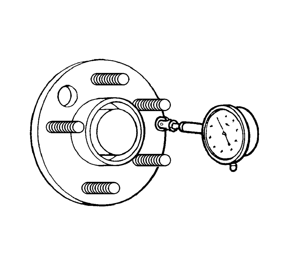
- Position the GE-8001 Dial Indicator Set , or equivalent, on the machined surface of the wheel hub/axle flange outside of the wheel studs.
- Rotate the hub one complete revolution in order to find the low spot.
- Set the GE-8001 Dial Indicator Set , or equivalent, to zero at the low spot.
- Rotate the hub one more complete revolution and measure the total amount
of wheel hub/axle flange runout.
Specification – Guideline
Wheel hub/axle flange runout tolerance guideline: 0.132 mm (0.005 in)
- If the runout of the wheel hub/axle flange IS within specification and the vehicle is equipped with wheel studs, proceed to step 13.
- If the runout of the wheel hub/axle flange IS within specification and the vehicle is equipped with wheel bolts, proceed to step 19.
- If the runout of the wheel hub/axle flange is marginal, the wheel hub may or may not be the source of the disturbance.
- If the runout of the wheel hub/axle flange is excessive, replace the wheel hub/axle flange. Measure the runout of the new wheel hub/axle flange.
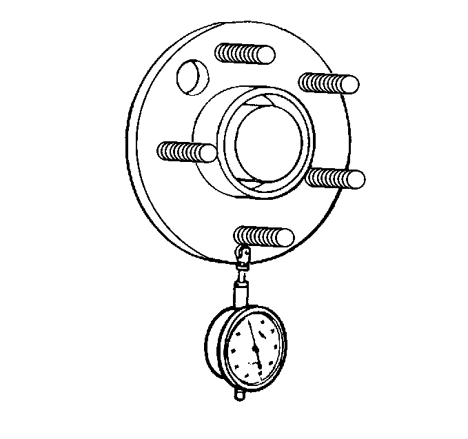
- Position the GE-8001 Dial Indicator Set , or equivalent, in order
to contact the wheel mounting studs.
Measure the stud runout as close to the flange as possible.
- Turn the hub one complete revolution to register on each of the wheel studs.
- Zero the GE-8001 Dial Indicator Set , or equivalent, on the lowest stud.
- Rotate the hub one more complete revolution and measure the total amount
of wheel stud – stud circle – runout.
Specification – Guideline
Wheel stud runout tolerance guideline: 0.254 mm (0.010 in)
- If the runout of the wheel studs – stud circle – is marginal, the wheel studs may or may not be contributing to the disturbance.
- If the runout of the wheel studs – stud circle – is excessive, replace the wheel studs as necessary. Measure the runout of the new wheel studs.
- Inspect the threads and the tapered seat portion on each of the wheel bolts for damage.
- Wheel bolts exibiting damaged threads and/or damaged tapered seats require replacement.
- Place the threaded portion of each wheel bolt along a straight edge to inspect for straightness.
- Wheel bolts that are not straight require replacement.
 Front Wheel Bearing and Hub Replacement
Special Tools
CH-50559 Wheel Hub/Bearing Remover Kit
For equivalent regional tools, refer to Special Tools.
Removal Procedure
Raise and support the vehicle. Refer to Lifting and Jac ...
 Rear Wheel Bearing and Hub Replacement (Disc Brake)
Special Tools
EN–45059 Angle Meter
For equivalent regional tools, refer to Special Tools.
Removal Procedure
Raise and suitably support the vehicle. Refer to Lifting and Jacking
...
Other materials:
Hazard Warning Flashers
(Hazard Warning Flasher): Press
and momentarily hold this button to make the front and rear turn signal lamps flash
on and off. This warns others that you are having trouble. Press and momentarily
hold again to turn the flashers off. ...
Drivetrain and Front Suspension Frame Replacement
Special Tools
EN-45059 Angle Meter
For equivalent regional tools, refer to Special Tools.
Removal Procedure
Support the radiator and condenser from above using the upper brackets
on each side.
Raise the vehicle on a hoist. Refer to Lifting and Jacking the Vehicle.
Re ...
Brake Rotor Assembled Lateral Runout Correction - On Vehicle Lathe
Special Tools
CH-45101-100 Conical Brake Rotor Washers
For equivalent regional tools, refer to Special Tools.
Warning: Refer to Brake Dust Warning.
Note:
Brake rotor thickness variation MUST be checked before checking
for assembled lateral runout (LRO). Thickness ...

0.0062