Chevrolet Sonic Repair Manual: Hub/Axle Flange and Wheel Stud Runout Inspection
Special Tools
GE-8001 Dial Indicator Set , or equivalent
- Raise and support the vehicle. Refer to Lifting and Jacking the Vehicle.
- Mark the location of the wheels to the wheel studs and mark the specific vehicle position on each tire and wheel â LF, LR, RF, RR.
- Remove the tire and wheel assemblies from the vehicle. Refer to Tire and Wheel Removal and Installation.
- Remove the brake rotors and/or brake drums from the vehicle. Clean the mounting surfaces of the brake rotors, the brake drums, if equipped, and the hub/axle flanges of any loose debris, rust, and corrosion.
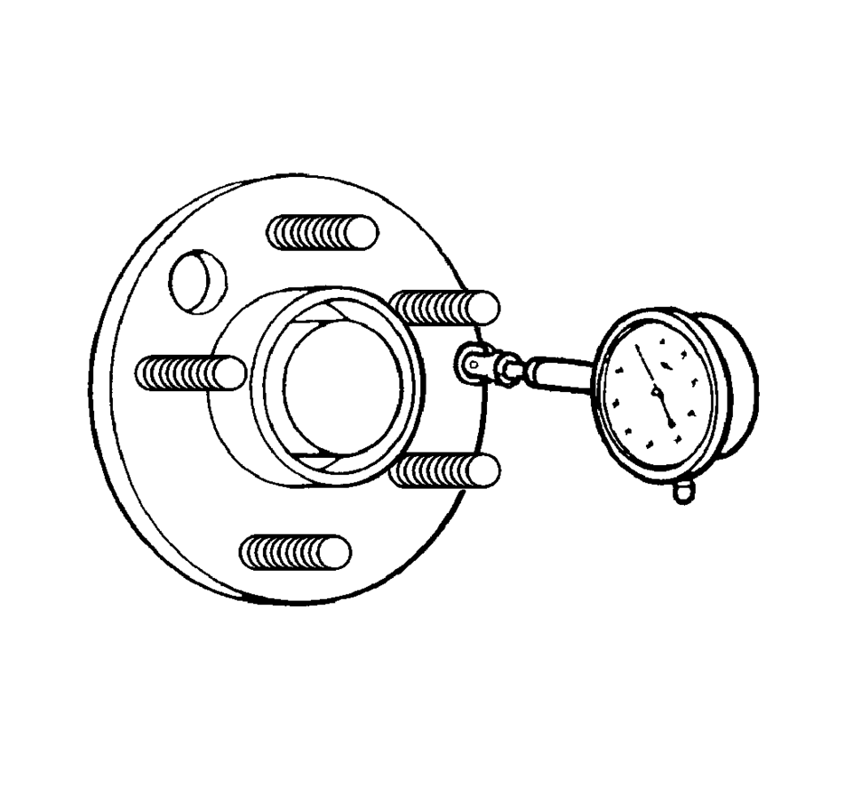
- Position the GE-8001 Dial Indicator Set , or equivalent, on the machined surface of the wheel hub/axle flange outside of the wheel studs.
- Rotate the hub one complete revolution in order to find the low spot.
- Set the GE-8001 Dial Indicator Set , or equivalent, to zero at the low spot.
- Rotate the hub one more complete revolution and measure the total amount
of wheel hub/axle flange runout.
Specification â Guideline
Wheel hub/axle flange runout tolerance guideline: 0.132 mm (0.005 in)
- If the runout of the wheel hub/axle flange IS within specification and the vehicle is equipped with wheel studs, proceed to step 13.
- If the runout of the wheel hub/axle flange IS within specification and the vehicle is equipped with wheel bolts, proceed to step 19.
- If the runout of the wheel hub/axle flange is marginal, the wheel hub may or may not be the source of the disturbance.
- If the runout of the wheel hub/axle flange is excessive, replace the wheel hub/axle flange. Measure the runout of the new wheel hub/axle flange.
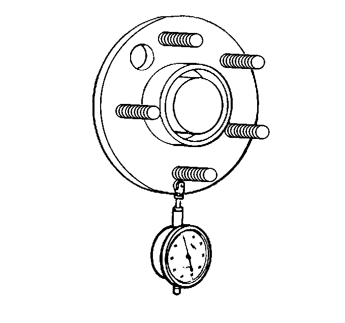
- Position the GE-8001 Dial Indicator Set , or equivalent, in order
to contact the wheel mounting studs.
Measure the stud runout as close to the flange as possible.
- Turn the hub one complete revolution to register on each of the wheel studs.
- Zero the GE-8001 Dial Indicator Set , or equivalent, on the lowest stud.
- Rotate the hub one more complete revolution and measure the total amount
of wheel stud â stud circle â runout.
Specification â Guideline
Wheel stud runout tolerance guideline: 0.254 mm (0.010 in)
- If the runout of the wheel studs â stud circle â is marginal, the wheel studs may or may not be contributing to the disturbance.
- If the runout of the wheel studs â stud circle â is excessive, replace the wheel studs as necessary. Measure the runout of the new wheel studs.
- Inspect the threads and the tapered seat portion on each of the wheel bolts for damage.
- Wheel bolts exibiting damaged threads and/or damaged tapered seats require replacement.
- Place the threaded portion of each wheel bolt along a straight edge to inspect for straightness.
- Wheel bolts that are not straight require replacement.
 General Description
The factory installed tires are designed to operate satisfactorily with loads
up to and including the full rated load capacity when these tires are inflated to
the recommended pressures.
The fol ...
 Lead/Pull Description
At a constant highway speed on a typical straight road, lead/pull is the amount
of effort required at the steering wheel to maintain the vehicle's straight path.
Important: Vehicles will t ...
Other materials:
Radio/Audio System Description and Operation
The entertainment system on this vehicle may have several different configurations
available to it. To determine the specific configuration of the vehicle, please
see the Service Parts ID Label, and refer to RPO Code List.
Each item in the list below represents topics covered in detail below. ...
Communication Interface Module Battery Replacement
Communication Interface Module Battery Replacement
Callout
Component Name
Preliminary Procedure
Remove the instrument panel lower compartment. Refer to
Instrument Panel Lower Compartment Replacement
1
...
OnStar Description and Operation
This OnStarÂŽ system consists of the following components:
Telematics communication interface control module
OnStarÂŽ three button assembly
Microphone
Cellular antenna
Navigation antenna
BluetoothÂŽ antenna (If equipped)
Back up battery (If equipped)
This system also interfaces wi ...

0.0058