Chevrolet Sonic Repair Manual: Hub/Axle Flange and Wheel Stud Runout Inspection
Special Tools
GE-8001 Dial Indicator Set , or equivalent
- Raise and support the vehicle. Refer to Lifting and Jacking the Vehicle.
- Mark the location of the wheels to the wheel studs and mark the specific vehicle position on each tire and wheel ?ELF, LR, RF, RR.
- Remove the tire and wheel assemblies from the vehicle. Refer to Tire and Wheel Removal and Installation.
- Remove the brake rotors and/or brake drums from the vehicle. Clean the mounting surfaces of the brake rotors, the brake drums, if equipped, and the hub/axle flanges of any loose debris, rust, and corrosion.
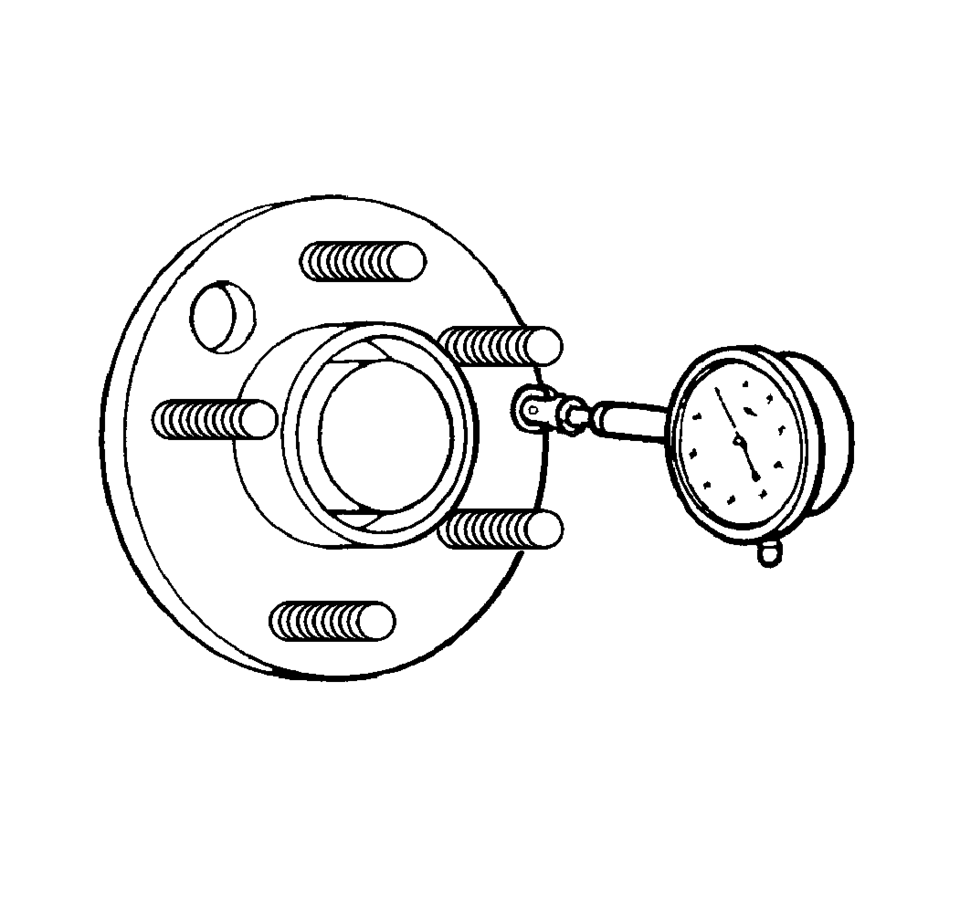
- Position the GE-8001 Dial Indicator Set , or equivalent, on the machined surface of the wheel hub/axle flange outside of the wheel studs.
- Rotate the hub one complete revolution in order to find the low spot.
- Set the GE-8001 Dial Indicator Set , or equivalent, to zero at the low spot.
- Rotate the hub one more complete revolution and measure the total amount
of wheel hub/axle flange runout.
Specification ?EGuideline
Wheel hub/axle flange runout tolerance guideline: 0.132 mm (0.005 in)
- If the runout of the wheel hub/axle flange IS within specification and the vehicle is equipped with wheel studs, proceed to step 13.
- If the runout of the wheel hub/axle flange IS within specification and the vehicle is equipped with wheel bolts, proceed to step 19.
- If the runout of the wheel hub/axle flange is marginal, the wheel hub may or may not be the source of the disturbance.
- If the runout of the wheel hub/axle flange is excessive, replace the wheel hub/axle flange. Measure the runout of the new wheel hub/axle flange.
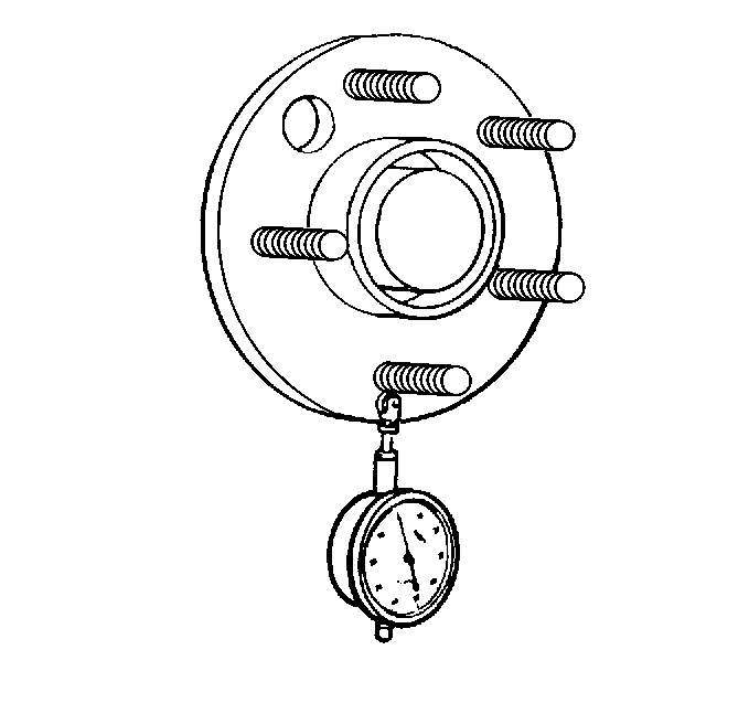
- Position the GE-8001 Dial Indicator Set , or equivalent, in order
to contact the wheel mounting studs.
Measure the stud runout as close to the flange as possible.
- Turn the hub one complete revolution to register on each of the wheel studs.
- Zero the GE-8001 Dial Indicator Set , or equivalent, on the lowest stud.
- Rotate the hub one more complete revolution and measure the total amount
of wheel stud ?Estud circle ?Erunout.
Specification ?EGuideline
Wheel stud runout tolerance guideline: 0.254 mm (0.010 in)
- If the runout of the wheel studs ?Estud circle ?Eis marginal, the wheel studs may or may not be contributing to the disturbance.
- If the runout of the wheel studs ?Estud circle ?Eis excessive, replace the wheel studs as necessary. Measure the runout of the new wheel studs.
- Inspect the threads and the tapered seat portion on each of the wheel bolts for damage.
- Wheel bolts exibiting damaged threads and/or damaged tapered seats require replacement.
- Place the threaded portion of each wheel bolt along a straight edge to inspect for straightness.
- Wheel bolts that are not straight require replacement.
 Axles
Axles
...
 Rear Brake Hose Replacement (Axle to Caliper)
Removal Procedure
Warning: Refer to Brake Dust Warning.
Warning: Refer to Brake Fluid Irritant Warning.
Raise and support the vehicle. Refer to Lifting and Jacking the ...
Other materials:
Windows
Manual Windows
If equipped, use the window crank to open and close each window.
See Manual Windows.
Power Windows
If equipped, press the switch down to open the window. Pull the front of the
switch up to close it.
The switches work when the vehicle is in ON/RUN or ACC/ ACCESSORY, or when Re ...
Rear Compartment Lid Adjustment
Rear Compartment Lid Adjustment
Callout
Component Name
1
Rear Compartment Lid
Caution: Refer to Fastener Caution
Procedure
Loosen the rear compartment lid hinge bolts (Qty:?€‰4) to adjust
the ...
Rear Side Door Opening Floor Carpet Retainer Replacement
Rear Side Door Opening Floor Carpet Retainer Replacement
Callout
Component Name
Preliminary Procedure
Remove the rear seat cushion. Refer to Rear Seat Cushion Removal and
Installation.
1
Rear Si ...

0.0058