Chevrolet Sonic Repair Manual: Master Cylinder Bench Bleeding
- Secure the mounting flange of the brake master cylinder in a bench vice so that the rear of the primary piston is accessible.
- Remove the master cylinder reservoir cap and diaphragm.
- Install suitable fittings to the master cylinder ports that match the type of flare seat required and also provide for hose attachment.
- Install transparent hoses to the fittings installed to the master cylinder ports, then route the hoses into the master cylinder reservoir.
- Fill the master cylinder reservoir to the maximum fill level with brake fluid from a clean, sealed brake fluid container. Refer to Master Cylinder Reservoir Filling.
- Ensure that the ends of the transparent hoses running into the master cylinder reservoir are fully submerged in the brake fluid.
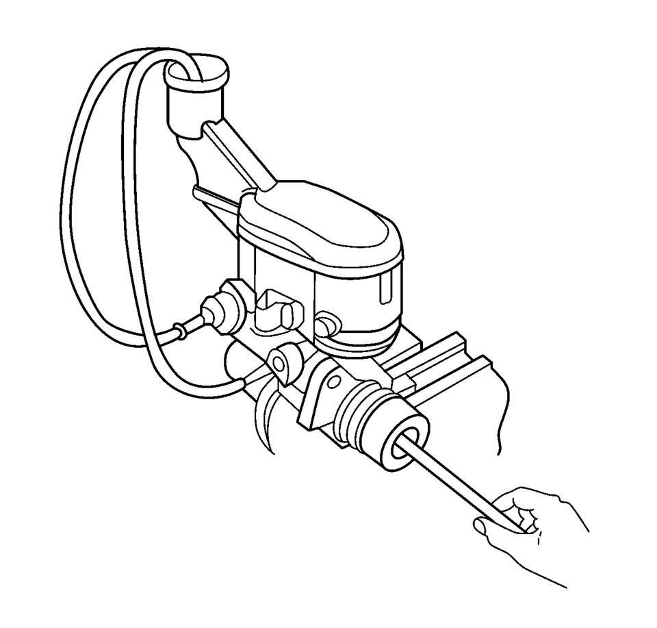
- Using a smooth, round-ended tool, depress and release the primary piston
as far as it will travel, a depth of about 25 mm (1 in), several times. Observe
the flow of fluid coming from the ports.
As air is bled from the primary and secondary pistons, the effort required to depress the primary piston will increase and the amount of travel will decrease.
- Continue to depress and release the primary piston until fluid flows freely from the ports with no evidence of air bubbles.
- Remove the transparent hoses from the master cylinder reservoir.
- Install the master cylinder reservoir cap and diaphragm.
- Remove the fittings with the transparent hoses from the master cylinder ports. Wrap the master cylinder with a clean shop cloth to prevent brake fluid spills.
- Remove the master cylinder from the vice.
Warning:
Refer to Brake Fluid Irritant Warning.
Caution:
Refer to Brake Fluid Effects on Paint and Electrical Components Caution.
 Brake Warning System Description and Operation
Brake Warning Indicator
Brake Warning Block Diagram
B80Park
Brake
SwitchB20Brake
Fluid Level
SwitchK9Body
Control
ModuleP16Inst ...
 Master Cylinder Replacement
Removal Procedure
Warning: Refer to Brake Fluid Irritant Warning.
Caution: Refer to Brake Fluid Effects on Paint and Electrical
Components Caution.
Place the ignit ...
Other materials:
Adhesive Installation of Rear Windows
Warning: Refer to Glass and Sheet Metal Handling Warning.
Use a urethane adhesive systems which meet GM Specification GM?€‰3651G.
Remove all mounds or loose pieces of urethane adhesive from the pinchweld
area.
If the original window is being reused, remove all but approxi ...
Front Side Door Window Regulator Handle Replacement
Front Side Door Window Regulator Handle Replacement
Callout
Component Name
1
Front Side Door Window Regulator Handle Clip
Procedure
Use the appropriate tool, remove the clip from handle.
2
...
Manual Transmission Shift Lever and Selector Lever Cable Adjustment
Remove the floor console. Refer to
Front Floor Console Replacement.
Lift upward and disengage (do not remove) both cable lock
adjusters (1) to release the internal cable assembly, one for each side.
Block the shift control housing, push the selector lever ( ...

0.0057