Chevrolet Sonic Repair Manual: Mode Control Cam Replacement
|
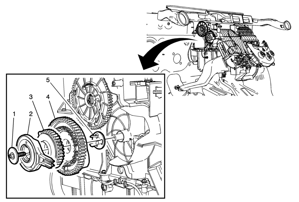
Callout |
Component Name |
|---|---|
Preliminary Procedures
|
|
|
1 |
Heater and A/C Control Mode Cam Screw Caution: Refer to Fastener Caution.
1.2 Y (11 lb in) |
|
2 |
Heater and A/C Control Mode Cable |
|
3 |
Heater and A/C Control Mode Cam Inner Gear |
|
4 |
Heater and A/C Control Mode Cam Outer Gear |
|
5 |
Heater and A/C Control Mode Cam Inner Gear Retainer |
 Manual HVAC Description and Operation
The air temperature and the air delivery description and operation are divided
into five areas:
HVAC Control Components
Air Speed
Air Delivery
Heating and A/C Operation
Recirculation Op ...
 Sun Load Temperature Sensor Replacement
Sun Load Temperature Sensor Replacement
Callout
Component Name
1
Sun Load Temperature Sensor Bezel
2
...
Other materials:
Intermediate Steering Shaft Replacement
Intermediate Steering Shaft Replacement
Callout
Component Name
Preliminary Procedure
Remove the steering column and the intermediate steering shaft as an
assembly. Refer to Steering Column Replacement.
1
...
Transmission Assemble (Gen 1)
Special Tools
3-9506289 Universal Adapter
R-0007758 Holding Fixture
S-9407197 Differential Rotating Tool
S-9407198 Differential Bearing Race Wrench
For equivalent regional tools, refer to Special Tools.
Install the clutch and differential housing assembly (1)
onto ...
Basic information
Example
Example
WARNING
In the Nissan Armada, improper adjustment of the HUD brightness or position
may obstruct the driver’s forward visibility through the windshield, increasing
the risk of accidents that could lead to serious injury or death.
Do not focus on the Head U ...

0.0056