Chevrolet Sonic Repair Manual: Parking Brake Adjustment (Disc Brake)
Note:
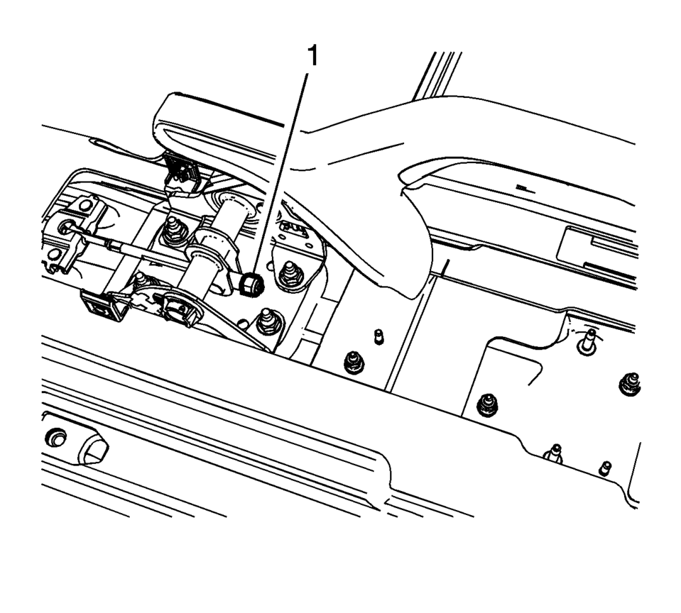
The park brake cable adjusting nut is a nylon lock type. Use ONLY HAND TOOLS whenever tightening or loosening the adjusting nut.
- Apply and fully release the park brake several times. Verify that the park brake lever releases completely.
- Turn ON the ignition. Verify the red BRAKE warning lamp is not illuminated.
- If the red BRAKE warning lamp is illuminated, verify the following:
- The park brake lever is in the fully released position and against the stop.
- There is no slack in the park brake cables.
- One of the tire and wheel assemblies should not rotate forward or rearward.
- The other tire and wheel assembly should not rotate forward or rearward, or should require substantial effort to rotate.
 Front Disc Brake Mounting and Hardware Inspection
Warning: Refer to Brake Dust Warning.
Inspect the fluid level in the brake master cylinder reservoir.
If the brake fluid level is midway between the maximum-full point and the
...
 Parking Brake Cable Replacement (Disc Brake)
Removal Procedure
Remove the front floor console. Refer to Front Floor Console Replacement.
Ensure that the parking brake lever is in the fully released position.
Using ...
Other materials:
Connection Settings
Select and the following may display:
Bluetooth Settings
Change Ringtone
Ringtone Volume
Bluetooth Settings
Select this feature to:
Connect, disconnect, or delete a device
Change or set a Personal Identification Number (PIN)
Turn on or off the Bluetooth connection
Check the dev ...
Hood Side Seal Replacement
Hood Side Seal Replacement
Callout
Component Name
1
Hood Side Seal Push-In Retainer (Qty:?€‰6)
2
Hood Side Seal
...
Replacing LATCH System Parts After a Crash
Warning: A crash can damage the LATCH system in the vehicle. A damaged
LATCH system may not properly secure the child restraint, resulting in serious
injury or even death in a crash. To help make sure the LATCH system is working
properly after a crash, see your dealer to have the system ...

0.0069